


MGS-150 Manual
6309-9000 Rev 2
29
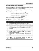
6.4. Calculating Calibration Voltage
Sensor outputs are linear. As long as you have a gas cylinder of known
concentration you can calibrate to any desired range.
Example:
For a sensor range of 0-1000 ppm and a cylinder of the target
gas at 800 ppm:
𝐕𝐨𝐥𝐭𝐚𝐠𝐞
=
𝐓𝐚𝐫𝐠𝐞𝐭
𝐆𝐚𝐬
𝐕𝐚𝐥𝐮𝐞
×
𝟓
𝐕
𝐒𝐞𝐧𝐬𝐨𝐫
𝐑𝐚𝐧𝐠𝐞
𝐕𝐨𝐥𝐭𝐚𝐠𝐞
=
𝟖𝟎𝟎
𝐩𝐩𝐦
×
𝟓
𝐕
𝟏𝟎𝟎𝟎
𝐩𝐩𝐦
=
𝟒
𝐕
So the output voltage signal should be adjusted to 4V.
6.5. Calibrating Semiconductor (SC) Sensors
Step
Calibrating Semiconductor (SC) Sensors
1
Locate Pot P2 which is used to adjust the zero point.
2
Monitor the output between 0V (negative) and VS (positive).
3
Adjust Pot P2 to 0 V or slightly positive (0.01 V is acceptable).
4
Locate Pot P3 which is used to calibrate the range (span) of
the sensor.
5
Monitor the output between 0V (negative) and VS (positive).
6
Expose the sensor to calibration gas and allow to stabilize
(approximately 3 minutes).
7
Adjust pot P3 to the voltage calculated in section 6.4 (page
29).
NOTE:
For semiconductor sensors, you MUST use
calibration gas in a balance of air (
not
N
2
).
Summary of Contents for MGS-150
Page 10: ...MGS 150 Manual 10 6309 9000 Rev 2 Figure 2 EC or IR Sensor Components and Wiring...
Page 11: ...MGS 150 Manual 6309 9000 Rev 2 11 Figure 3 SC Sensor Components and Wiring...
Page 18: ...MGS 150 Manual 18 6309 9000 Rev 2 Figure 5 IP66 Housing with Splashguard...
Page 33: ...MGS 150 Manual 6309 9000 Rev 2 33...
Page 34: ...MGS 150 Manual 34 6309 9000 Rev 2...