


MGS-150 Manual
26
6309-9000 Rev 2
NOTE:
Prior to carrying out a bump test, check and adjust
the zero setting as described in the Calibration section.
NOTE:
Procedures for bump test and calibration vary
depending on the sensor technology used and the gas in
question. The MGS is available in three sensor versions:
Semiconductor (SC), Electrochemical (EC) and Infrared (IR).
NOTE:
Do not pressurize the sensor.
NOTE:
For semiconductor sensors, you MUST use
calibration gas in a balance of air (
not
N
2
).
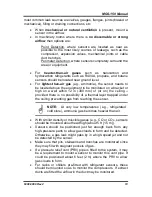
IMPORTANT:
After a semiconductor or electrochemical
sensor is exposed to a substantial gas leak, the sensor
should be checked and replaced if necessary.
NOTE:
To test the audible alarm and/or relay function, check
the delay is set at zero and expose to gas. You can mute the
audible alarm by removing jumper JP3.
Step
Bump Testing Using Calibration Gas Cylinders
1
Remove the enclosure lid of
the gas detector (not in an
exhaust area).
2
Connect a voltmeter to
monitor sensor response.
Monitor the response
between pins 0V and VS.
3
Expose the sensor to gas from the cylinder. You can place
the entire MGS into a plastic bag or use a plastic hose/hood
to direct gas to the sensor head. A response of above 80% is
acceptable.
Summary of Contents for MGS-150
Page 10: ...MGS 150 Manual 10 6309 9000 Rev 2 Figure 2 EC or IR Sensor Components and Wiring...
Page 11: ...MGS 150 Manual 6309 9000 Rev 2 11 Figure 3 SC Sensor Components and Wiring...
Page 18: ...MGS 150 Manual 18 6309 9000 Rev 2 Figure 5 IP66 Housing with Splashguard...
Page 33: ...MGS 150 Manual 6309 9000 Rev 2 33...
Page 34: ...MGS 150 Manual 34 6309 9000 Rev 2...