
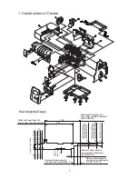


5. ADJUSTMENT OF STITCHES
Fabric : cotton 1-layer
Thread : 100% polyester spun thread (maxi-lock or metrosene thread)
Needle : SCHMEZ ELx705 90/14
Machine: 1-needle (right), 3-thread sewing
Width : 5.0mm (max)
Length : 3.0mm
D.F. : N
Stitch selector : B
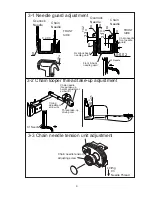
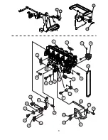
5-1 ADJUSTMENT OF NEEDLE THREAD SENSOR CABLE
The needle thread sensor cable effects the stitch drlivery length of both needle thread and
looper threads. You are required to adjust this cable first.
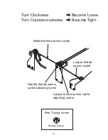
NOTE: The needle thread sensor cable adjusting screw works;
Turn clockwise and both needle & looper threads become loose.
Turn counter-clockwise and both needle & looper threads become tight.
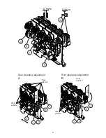
a) Line up the looper thread fine-tuning screw at the standard position.
b) Sew 1-layer of cotton with 1-needle (right) 3-thread as shown in the above
and adjust only the needle thread in the stitch not to have a puckering.
Disregard the looper threads in the stitch at this stage.
c) Then, adjust the looper thread sensor cable (5-2).
5-2 ADJUSTMENT OF LOOPER THREAD SENSOR CABLE
Before the adjustment of looper thread sensor cable, adjust the needle
thread sensor cable first (5-1).
NOTE: The looper thread sensor cable adjusting screw works;
* Turn clockwise and looper threads become loose.
* Turn counter-clockwise and looper threads become tight.
a) Line up the looper thread fine-tuning screw at the standard position.
b) Sew 1-layer of cotton with 1-needle (right) 3-thread as shown in the previous page and turn the
screw until you get the ideal stitch which looper threads are not loose and fabric is not curled.
c) After adjustment of looper thread sensor cable, the stitch delivery length of needle thread
might be changed. Therefore, check the needle thread sensor cable again (see 5-1).
11


