background image


B9Creations Core Series Printer User Manual  Rev. A-3 

04-14-2020 

Instructions for Safe Use 

2.1 

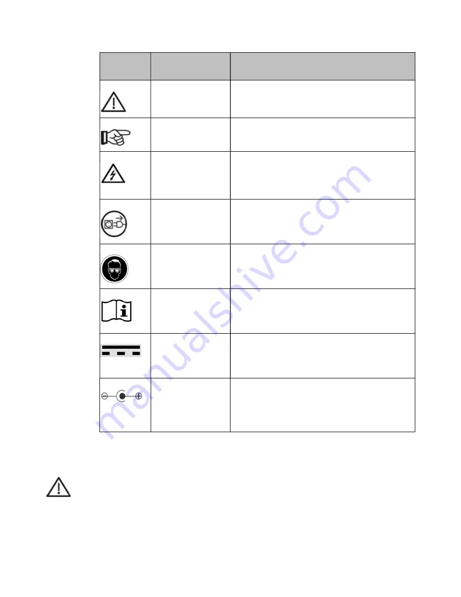
Explanation of Symbols 


2.2 

Transport Damage 

Upon receipt of the equipment, check the unit for transport damage.  If damage is found to either the 

equipment or its shipping container, accept the unit with caution. Report the potential damages to the 
shipper and B9Creations, LLC ([email protected]) within 24 hours after receiving the unit. 


CAUTION 

Do not work with a damaged unit under any circumstances. 
 

2.3 

Operator’s Obligations 

In addition to complying with the statutory regulations specified by the manufacturer, the operator must 
ensure the statutory obligations are observed and implemented at the work place, i.e. the operator must 

train personnel and comply with industrial safety legislation and any other regulations or laws in force. 

Symbol


Accompanying 
word(s)


Explanation


CAUTION


This symbol indicates safety-relevant paragraphs and 
sections in these working instructions


NOTE


This symbol indicates information within the working 

instructions that optimizes the use of the unit


WARNING


This symbol warns of the dangers of electric voltage.  

Failure to comply with safety guidelines and 
procedures can result in electrical shock that may 
lead to injury or death. 


DISCONNECT FROM 
MAINS


This symbol indicates danger of electric shock when 
unit enclosure is opened. Unplug the unit before 

opening it.


WEAR EYE 
PROTECTION 

This symbol indicates that eye protection is needed.  
Failure to comply with safety guidelines and 
procedures can result in injury to eyes. 


READ/REFER TO USER 
MANUAL 

This symbol directs the operator or service agent to 
read the User Manual for the equipment to find 

important information. 


DC POWER 

This symbol indicates the equipment utilizes DC 
Power. 


DC JACK POLARIZED 

This symbol indicates that the DC power input jack 

for the equipment is polarized.  In particular, the DC 
power input jack’s outer conductor is the “negative” 
conductor and the inner conductor is “positive” 
conductor. 

Summary of Contents for B9 Core Series

Page 1: ...USER MANUAL B9 Core Series530 550...

Page 2: ...document may be either trademarks and or registered trademarks of the respective owners The publisher and the author make no claim to these trademarks While every precaution has been taken in the prep...

Page 3: ...n and Interface 11 5 1 Product Identification 11 5 2 Interface Elements 11 6 Transport and Installation 12 6 1 Transport 12 6 2 Hardware Setup 13 6 3 Software Setup 14 7 Operation 14 7 1 Turning the P...

Page 4: ...Print Library 23 9 12 2 Material and Quality 23 9 12 3 Prepare for Printing 23 9 12 4 Printing 23 9 13 Removing the Build Table and Printed Object from the Printer 24 9 14 Removing the Printed Object...

Page 5: ...B9Creations Core Series Printer User Manual Rev A 3 04 14 2020 15 Tips and Tricks 35 16 Service 35 17 Document History 35...

Page 6: ...ore has an integrated controller installed inside printer casing The software required for all the operations is pre installed and ready for use The provided AC DC power supply either model MeanWell G...

Page 7: ...ates safety relevant paragraphs and sections in these working instructions NOTE This symbol indicates information within the working instructions that optimizes the use of the unit WARNING This symbol...

Page 8: ...echnical connection requirements of the electrical supply companies etc CAUTION The connecting power supply cable and plug must be checked for damage prior to operation If any damage exists the unit m...

Page 9: ...Intended Use and Proper Operation 3 1 Intended Use The B9Creations Core Series printer utilizes light to create 3 d objects in a Photoinitiated liquid used in jewelry model making art prototyping and...

Page 10: ...of Delivery A B9Creations Core Series with external power supply cord set Build Table and 2 DuraVats B Installation Guide C Finishing Kit 4 2 Finishing kit components A Print Scraper 1x to remove prin...

Page 11: ...ing cured pieces from material L Clippers 1x to clean supports from print 5 Identification and Interface 5 1 Product Identification Manufacturer and electrical specification information Product Identi...

Page 12: ...riented properly to prevent damage Maximum stacking level of devices for shipment 3 Levels Do not stack additional items or shipments on top of devices Protect from rain Mechanical shock must be avoid...

Page 13: ...or blocked The rear of the unit must be at least 100 mm 4 away from any wall to avoid blocking air outlet of the built in fan A footprint area w x d 750 x 750 mm or 30 x 30 is required The printer ne...

Page 14: ...tware if not authorized by B9Creations LLC 7 Operation 7 1 Turning the Printer ON Turn on the rear mains On Off switch The Function Button on the front of the printer will illuminate and fade to off m...

Page 15: ...econd then repeats throughout duration of printing Indicates printer is finished printing Light blinks second On second Off repeat Indicates door open during printing Light blinks second On second Off...

Page 16: ...ses ONLY Do not use USB 2 0 or 3 0 portable dongles for mobile Internet Do not use the USB port to connect directly to a computer laptop or device other than a USB storage device dedicated for file tr...

Page 17: ...ted equipment 8 2 Operational Safety Features After completion of printing an object or after an aborted print printer cannot print another object until the door has been opened and closed It is the r...

Page 18: ...er Return to Previous Menu Return to Home Menu Continue to next Menu File Information Discard File File USB File Transfer Print History Settings Network Information Secure Unsecure and Network Signal...

Page 19: ...k connection type may take a few moments The operator must select a valid Wi Fi Network name in the Wi Fi Network field A list of active Wi Fi networks will be displayed if the operator presses the fi...

Page 20: ...s the Gateway IP address and the Subnet Mask NOTE Instead of manually entering the addresses and information in the setting fields it is often best to press the box to the right of Auto DHCP and Apply...

Page 21: ...o seconds will display a menu icon to delete one or more print objects 9 8 2 Pressing on the print picture in the right pane will display delete menu icons Pressing Delete will delete the print job Pr...

Page 22: ...rvoir NOTE Do not overfill DuraVat Overfill of the DuraVat will cause material spillage in the build chamber Slide DuraVat into printing position in the build chamber DuraVat flanges should slide unde...

Page 23: ...he Print Library screen the operator will be directed to the Material and Quality screen On this screen the operator can select the approved material with which the part will be printed and the height...

Page 24: ...job or after selecting to Abort a print the touchscreen will display the Print Finished page NOTE For best printing results allow the DuraVat to recharge per section 10 1 4 after each print 9 13 Remov...

Page 25: ...achine Info Select Custom Name field Type in desired printer name My B9 Core 530 in this example 9 16 Changing Printer Language Select Settings on the Primary Menu Press Language Select the desired la...

Page 26: ...printer and may scratch critical glass surfaces 10 1 2 General DuraVat Cleaning The DuraVat should be kept clean and free of cured material suspended in the material Material should be removed from th...

Page 27: ...Do not scratch the DuraVat aperture surface Never use paper towels to clean the window NOTE Do not use any metal tools to remove cured material from the aperture CAUTION Wear protective gloves when u...

Page 28: ...ce the DuraVat if when Aperture contacting the print material becomes damaged Seal around aperture leaks Flanges that align the DuraVat in its proper position in the print chamber become damaged or wo...

Page 29: ...B9Creations Core Series Printer User Manual Rev A 3 04 14 2020 11 Work Flow for Printing...

Page 30: ...Size W x H x D 270 x 420 x 640 mm 10 7 x 16 5 x 25 25 Weight 21 kg 50 lbs Mains Input 100 240 VAC 50 60 Hz 1 4 0 7A Rated power of Printer 12VDC 5A Required table area W x D 750 x 750 mm 30 x 30 Packa...

Page 31: ...rder of listing in the table Error description Possible Causes Remedy 1 The printer does not turn on when pressing the Function button Printer has not completed booting up Check Function button to see...

Page 32: ...start printing Door Open Close door to start printing Prior print or aborted file not removed from printer See Sections 9 11 and 9 12 Clean Build Table Install Build Table in printer Close door Start...

Page 33: ...ck model in B9Create insure model is snapped to floor or foundation Error with Print model file Load and print Sample Print model If test model prints accurately stl model is not correct Remake stl fi...

Page 34: ...nce If none of the above solves the problem contact the B9Creations LLC support 8 USB Cpj files not transferring to the printer 1 Bad USB try a different USB 2 Verify printer USB operation If the prin...

Page 35: ...ble Use the B9Create Print Editor Help tab for useful information 16 Service Internet connection is required for Remote Support For information regarding support of your B9Creations Core Series visit...

Reviews: