background image

ArtiStar™ GU10

Anchor Base Installation 

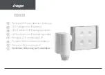
5.  Make two line voltage connections using 

proper wire connectors (By Others). Connect 

incoming ground wire to ground wire provided 

in fixture body. 

See wiring diagram.

6.  Place fixture onto mounted anchor base and 

press straight down until the two pieces are 

flush with each other. 
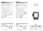
WIRING DIAGRAM

LINE

FIXTURE

COM

GROUND

LINE

COM

GROUND

RELEASED 

1-26-17

REFERENCE


NUMBER

INS131800

40429 Brickyard Drive • Madera, CA 93636 • USA

559.438.5800 • FAX 559.438.5900 

www.bklighting.com • [email protected]

B-K LIGHTING

IMPORTANT SAFETY INFORMATION LISTED ON REVERSE

READ, FOLLOW, AND SAVE ALL SAFETY AND INSTALLATION INSTRUCTIONS

THIS DOCUMENT CONTAINS PROPRIETARY INFORMATION OF B-K LIGHTING, INC. AND ITS RECEIPT OR POSSESSION DOES NOT CONVEY ANY RIGHTS TO REPRODUCE, DISCLOSE ITS CONTENTS, OR TO MANUFACTURE, USE OR SELL ANYTHING 

IT MAY DESCRIBE.  REPRODUCTION, DISCLOSURE OR USE WITHOUT SPECIFIC WRITTEN AUTHORIZATION OF B-K LIGHTING, INC. IS STRICTLY FORBIDDEN.

1.  Study anchor base plan. Prepare mounting 

surface for anchor base.

2.  Use 5/64” Allen wrench loosen three (3) #8-32 

stainless steel set screws (do not remove set 

screws from fixture base). Remove anchor base 

from bottom of fixture. 

3.  Pull branch circuit wiring necessary for 

installation (By Others). Feed branch circuit 

wiring through anchor base.

4.  Secure anchor base to solid surface (i.e. wood, 

concrete) using appropriate hardware for 

specific surface. 

Fixture Installation

7.  Use 3/16” Allen wrench to slightly loosen 

¼”-28 stainless steel black oxide socket head 

cap screw at the knuckle for vertical aiming 

purposes. Use 5/64” Allen wrench to loosen 

the three (3) #8-32 stainless steel set screws 

on anchor base. Rotate fixture at base and aim 

fixture to desired horizontal location.

8.  Tighten the three (3) #8-32 stainless steel set 

screws on anchor base and ¼”-28 stainless 

steel locking screw at the knuckle to secure all 

aiming positions.

PROJECT:

TYPE:


All line voltage connections must be made 

in compliance with the National Electrical 

Code. Failure to do so will void warranty.


Seal base to surface as per NEC.

Summary of Contents for ArtiStar GU10

Page 1: ...n unsafe condition The use of damaged components may cause an unsafe condition and void product warranty IMPORTANT SAFETY INFORMATION READ FOLLOW AND SAVE ALL SAFETY AND INSTALLATION INSTRUCTIONS Do not block light emanating from product in whole or part as this may cause an unsafe condition Never operate the fixture with missing or damaged lens Lens must be cleaned on regular basis Entire fixture...

Page 2: ...ON OF B K LIGHTING INC IS STRICTLY FORBIDDEN 1 Study anchor base plan Prepare mounting surface for anchor base 2 Use 5 64 Allen wrench loosen three 3 8 32 stainless steel set screws do not remove set screws from fixture base Remove anchor base from bottom of fixture 3 Pull branch circuit wiring necessary for installation By Others Feed branch circuit wiring through anchor base 4 Secure anchor base...

Page 3: ... whole or part as this may cause an unsafe condition Never operate the fixture with missing or damaged lens Lens must be cleaned on regular basis Entire fixture may become extremely hot Do not touch hot lens or fixture body Do not touch the lamp at any time Use a clean dry soft cloth to handle the lamp Oil from skin may damage the lamp and cause it to rupture Replace lamp only with correct wattage...

Page 4: ...a gravel or sand Concrete Finished grade Finished grade Stability Flange Pea gravel or sand Finished grade 5 Pour concrete By Others Label on Power Pipe indicates installation depth with finished grade 3 Pull primary branch circuit wiring to Power Pipe Allow for additional length to make connections to fixture leads and for future service Place Power Pipe in hole Finished grade Stability Flange Pe...

Page 5: ...ay cause an unsafe condition and void product warranty IMPORTANT SAFETY INFORMATION READ FOLLOW AND SAVE ALL SAFETY AND INSTALLATION INSTRUCTIONS Do not block light emanating from product in whole or part as this may cause an unsafe condition Never operate the fixture with missing or damaged lens Lens must be cleaned on regular basis Entire fixture may become extremely hot Do not touch hot lens or...

Page 6: ...e Suitable for installation into combustible materials Rated for 90 C Junction box universal mounting ring screws box mounting hardware and gaskets By Others 1 Install universal mounting ring supplied with fixture to junction box using appropriate hardware By Others Align canopy mounting holes to final mounting position Phase 2 Finish Installation of Fixture WIRING DIAGRAM LINE FIXTURE COM GROUND ...

Page 7: ...om skin may damage the lamp and cause it to rupture Replace lamp only with correct wattage and type of lamp marked on fixture label All gaskets O rings and sealing surfaces must be kept clean during installation and service failure to do this may cause an unsafe condition and void product warranty INSTRUCTIONS PERTAINING TO A RISK OF FIRE OR INJURY TO PERSONS IMPORTANT SAFETY INSTRUCTIONS Lighted ...

Page 8: ... INC IS STRICTLY FORBIDDEN IMPORTANT SAFETY INFORMATION READ FOLLOW AND SAVE THESE INSTALLATION INSTRUCTIONS ArtiStar Mounting System Standard Adjustment ArtiStar Knuckle Power Pipe Option 2 Use 3 16 Allen wrench to slightly loosen 28 stainless steel black oxide socket head cap screw at the knuckle for vertical aiming purposes 3 Tighten the three 3 8 32 screws on base with appropriate tool for mou...

Page 9: ...re wiring to power supply and during servicing or relamping turn off power at fuse or circuit breaker before service The use of accessory equipment not recommended by the manufacturer or installed contrary to instructions may cause an unsafe condition The use of damaged components may cause an unsafe condition and void product warranty IMPORTANT SAFETY INFORMATION READ FOLLOW AND SAVE ALL SAFETY A...

Reviews: