background image

Setting up the device

- Place the device on a flat surface, or mount it in a 19 inch flightcase or rack.
- Plug the AC/DC power converter (supplied) into the rear panel of the unit and plug the other end into a wall 
outlet or power distribution system.
- Connect your DMX-lighting by using XLR-XLR cables (Ayra recommends using special DMX 110 Ohm 
cables, such as Procab REF953). Daisy-chain all your DMX lighting until every fixture is connected. Set the 
correct DMX addresses (see the manuals of every individual product).
- Turn on the unit 

Physical fader assignment (OPTIONAL)

IT is possible to collect certain fixture attributes and control them by using just a few of your faders. This 
might come in useful when you use different fixtures with similar functions, on different channels. This way 
you are able to patch certain DMX-channels (functions) to a certain control channel of your DMX console. 

This function is useful for movement (pan/tilt), gobo change, color change, color mix, dimming and strobe 
features of your DMX fixtures.

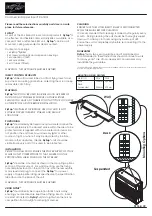
1. Press and hold the RECORD button.
2. While holding the RECORD button, press flash button 6 three times
3. While in this mode, press the Flash button that you wish to assign the DMX channel output to.
4. While holding RECORD, press the Flash button corresponding to the DMX output that you wish to assign 
the fader to.
5. Repeat steps 2-3 as often as necessary.
6. Press and hold  Exit to exit this mode

1. Press and hold the RECORD button, press fader 6 three times
2. Press flash button 1
3. While holding the RECORD button, press Flash button 5
4. You assigned fader 1 to DMX channel 5
5. Press and hold  Exit to exit the mode

NOTE: 

All physical faders can be assigned to output on a different DMX-channel. For optimal control, you 

are able to place a different label on the controller.
You can check what the assignment of a certain channel is, by pressing the Fader button of the 
corresponding channel while in this mode
There is no limit to the amount of channels that can be assign to a single fader. You are able to assign all 48 
DMX-channels to one fader.
CHNO corresponds to the physical channel fader. SLDNO corresponds to the DMX output channel

Switching between Page A and Page B (1-24, 25-48)

Press and hold the RECORD button. While doing that, press the PAGE A-B button. If you are on page A, you
will go to page B and vice versa. 
Page A: 1-24
Page B: 25-48
There is an additional set of 4 pages on page B, for playback control

NOTE:

 When the controller turns on, it will display the last used page

Any information and illustrations shown in this user manual are subject to change without further notice.

User manual version: 2.0

Creation date + author initials: 29-03-2014 RV Revision date + author initials: 29-03-2014 RV

Summary of Contents for OSO SCENE 48

Page 1: ...User manual Any information and illustrations shown in this user manual are subject to change without further notice User manual version 2 0 Creation date author initials 29 03 2014 RV Revision date a...

Page 2: ...nected Do not cover or remove the ground contact Never leave cables lying around Do not open the device and do not modify any hard or software of this unit Do not insert this object into air vents Do...

Page 3: ...the device while in use Avoid brute force during the installation and operation of this device Familiarize yourself with the functions of the device before use Do not allow operation of the device by...

Page 4: ...electrical shocks and short circuit Always mount the fuse cover back to the fuse compartment Any information and illustrations shown in this user manual are subject to change without further notice Us...

Page 5: ...at should be included is missing contact your local dealer for help If the box appears severely damaged soaked with liquid or ripped apart do not unpack the product and contact your local dealer for h...

Page 6: ...Any information and illustrations shown in this user manual are subject to change without further notice User manual version 2 0 Creation date author initials 29 03 2014 RV Revision date author initia...

Page 7: ...tton 13 24 37 48 Changes the value of channels 13 24 37 48 to 100 while holding 6 Down Beat Rev Down function to modify a scene in EDIT mode Beat Rev Used to reverse the chasing direction during playb...

Page 8: ...es 0 18 Home Deactivates the Blind on a given channel 19 Park Used to select Single Mix chase Used to bring channel 13 24 37 48 to full of current setting Used to program a scene into the Master B sli...

Page 9: ...ted MIDI data trough 5 MIDI IN MIDI port to receive MIDI information from an external device 6 MIDI OUT MIDI port to send MIDI information to an external device 7 AUDIO IN RCA mono connector capable o...

Page 10: ...arcans MIDI A standard of presenting musical information in digital format Also capable of sending certain control signals from one device to another and vice versa Stand Alone The function of a fixtu...

Page 11: ...ponding to the DMX output that you wish to assign the fader to 5 Repeat steps 2 3 as often as necessary 6 Press and hold RECORD Exit to exit this mode 1 Press and hold the RECORD button press fader 6...

Page 12: ...rd button Edit enable 1 Enable the RECORD mode see above 2 Use the Page button to select the page where the program that you wish to edit is located 3 Tap the Mode Select button to select Chase Scenes...

Page 13: ...Insert button to insert the step s you just created before 5 Exit the EDIT mode NOTE See above for more information about entering the EDIT mode Modify a step or multiple steps 1 Enter the EDIT mode s...

Page 14: ...ne signal from a music signal source such as a PA or DJ mixer Playing a scene with the speed slider 1 Select your scene as described above 2 Move the Speed slider to SHOW MODE position full down 3 Pre...

Page 15: ...the channel will light up indicating that the auxiliary has been assigned 5 Exit the RECORD mode see above Note Refer to the display to see the functions that are currently being edited Note Press 7...

Page 16: ...I control channel 1 16 by tapping Flash button 1 16 The relevant LED will light up and confirm the setting 3 While holding down Record tap the REC Exit button to leave the MIDI setting NOTE This is th...

Page 17: ...e before the transfer is completed NOTE Once the right mode on both devices is selected the FILE DUMP process will start automatically NOTE During FILE DUMP all other functions are disabled and will n...

Page 18: ...our DMX controller Faulty positioning of the DMX polarity switch on the controller flip the polarity switch on your DMX controller No response or DMX activity signal LEDs active Check your DMX cables...

Page 19: ...he reset program This will reset all values to the original 0 point The fixture does not respond fast enough to the set speed on my DMX controller Moving parts can not keep up with the set speed Decre...

Page 20: ...sync autorun MIDI IN OUT 19 inch mounting brackets hidden behind covers on both sides 6U height DMX polarity selector data pin inversion Weight and dimensions dimensions 485 x 290 x 98 mm 19 inch rack...

Reviews: