GB
Fig. 3 Fig. 4
6.
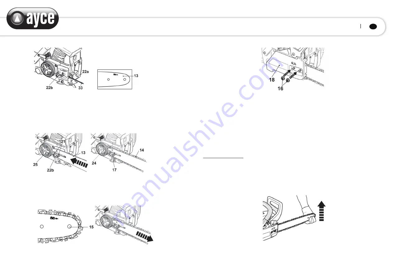
Place the slot in the guide bar (13) over the two bolts (21). Push the guide bar (13) to the left
towards the sprocket (24) (behind the clutch (25)). Make sure the tension pin (22b) is inserted
into the lower hole on the guide bar (Fig. 5).
7.
Place the saw chain (14) over the sprocket (24) behind the clutch (25) and fit around the guide
bar (13). Make sure the chain is placed above the chain catcher (17) (Fig. 6).
Fig. 5 Fig. 6
8.
The saw chain movement is as indicated by the arrow (Fig. 7). Make sure the chain is properly
placed over the sprocket nose (15) of the guide bar (13).
9.
Pull the guide bar (13) carefully towards the right to tighten the saw chain (14) (Fig. 8).
Fig. 7 Fig. 8
10.
Refit the cover (18). Fix it with the retaining nuts (16) (Fig. 9).
Fig. 9
WARNING!
Always carry out a test run before starting work and after every tool change! Always ensure that
the tools are in good condition, correctly mounted and able to turn freely. The trial run should be at
last 30 sec.
Adjusting chain tension
WARNING!
The saw chain has very sharp edges. Use protective gloves for safety.
Saw chain tensioning
1)
Always check the saw chain tension before use, after the first cuts and regularly during use,
approx. every five cuts. Upon initial operation, new chains can lengthen considerably. This is
normal during the break-in period and the interval between future adjustments will lengthen
quickly.
2)
Lift up the tip of the guide bar (13) and keep it there as you adjust the tension (Fig. 10).
Fig. 10
3)
Turn the tension screw (22a) until the chain ‘tie straps’ are just touching the bottom edge of
the guide bar (13) (Fig. 11, 12).
140 141


