– 4 –
– 5 –
B) When using Low-Level signal (also referred to as RCA inputs), connect the blue colored remote
wire from the ATB25RS to the vehicles head unit. This way the ATB25RS will turn on and off
automatically with the system.
2. Connect the remote control in order to adjust the audio volume level.
3. Fix the cable holder bar in order to secure the Plug&Play connecting harness. Please be aware
of not using this bar can lead to a damage of the harness and result then in a defect of the
ATB25RS or even in a fire.
MOUNTING ACCESSORIES
For quickest and most convenient installation we suggest to use the Velcro strips. Velcro stripes
are quickly installed, save and you don’t need any tool to fix or release it. Just lead the Velcro strips
through the spare wheels spokes, place the ATB25RS inside the wheel (you may need to use the
alignment plate too) and fix the Velcro as shown in the diagram.
INSTALLATION PROCEDURE
-3-
-2-
Use the supplied cable and wire harness and connect the outputs properly as
shown in the High-Level& Low-Level inputs wiring diagram as following.
Use only one of the audio inputs, otherwise, it may lead to audio interference.
15A
SPECIFICATION
Model
Supply Voltage
Peak Power
Enclosure
Impedance
Frequency Response
Variable crossover frequencies
S/N Ratio
Input Level
Fuse
Phase
Speaker Size
CF-A16
14.4V D.C.
380 Watts
Sealed
2
Ω
(Single Speakers)
30Hz-150Hz
50Hz-150Hz
92dB
Speaker and RCA level inputs
15A
0
0/180
Single 10 inches woofers(254mm x 254mm)
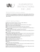
We strongly suggest you have the active subwoofer professionally installed,but if you
are doing it solo this section lists the procedures you’ll need to install the subwoofer
in your vehicle.
Continuos listening at high sound level(above 110dB) can durably damage your hearing.
Listening above 130dB can damage your hearing permanently.
This subwoofer maybe installed only in the spare wheel well, and it is designed to fit
an above 15-inches rim spare tire.
INSTALLATION GUIDE
Warning
Note
12V
BATT
Fuse
15A
Speaker
Left channel output wire
Speaker
Right channel output wire
Audio Device
Black wire (Power-) near to metal part of vehicle body
Red wire
White/black(-)
and whit wire(+)
Gray/black(-) and Gray wire(+)
Blue wire
= REM input
Audio Device
12V
BATT
Fuse
Black wire (Power-) near to metal part of vehicle body
Red wire
RCA Signal wire
Blue wire
Audio device control wire
=
PWR
SUB LEVEL
PWR
SUB LEVEL
1) Wiring Diagram1(High level input)
A) With control via the High Level Inputs, first the speaker harness will need to
be spliced the wire side of the splitter. Then connect the white wire to the left
(+),white/black wire to the left(-)(it can be identified whether the left or right
channel via the attached harness label), grey to the right(+), and grey/blace to
the right(-)corresponding vehicle wires, and finally plug the supplied harness
into the High-Level Inputs/power matching connector on the amplifier panel of
the subwoofer.
2) Wiring Diagram2(Low level “RCA” input)
B) With control via the Low Level Inputs(also referred to as RCA Inputs),connect
the blue color remote wire from the Spare wheel active subwoofer to the vehicle’s
head unit so The CF-A16 will turn on and off with systems.
If you cannot use the Velcro strips, the ATB25RS is provided with an alignment plate, a M8 screw and
nut in order to fix it in various ways.
DIAGRAM Low-Level
Installation 2
Sehr geehrter Kunde
Vielen Dank für das Vertrauen, das Sie uns mit dem Kauf des AXTON ATB25RS entgegengebracht
haben. Der AXTON Aktiv-Subwoofer wurde speziell für den Einsatz in mobilen Soundsystemen mit
einer 12-Volt-Stromversorgung (mit negativer Chassis Masse) entwickelt. Damit Sie sich mit den
technischen Eigenschaften und klanglichen Feinheiten Ihres Aktiv-Subwoofers vertraut machen kön-
nen, empfehlen wir Ihnen, diese Einbau- und Bedienungsanleitung vor der Installation sorgfältig
durchzulesen. Sollten beim Einbau oder bei den Einstellungen dennoch Fragen oder Probleme auf-
tauchen, wenden Sie sich bitte an Ihren Axton-Fachhändler.
PACKUNGSINHALT
Nach dem Auspacken empfehlen wir eine Überprüfung von Anzahl und Zustand des Packungsin-
halts:
n
ATB25RS Aktivsubwoofer
n
Bass Boost Fernsteuerungseinheit
n
1 Plug&Play Anschlusskabelset
n
1x M8 x 50 mm mit Mutter (zur Montage des ATB25RS in der Reserveradmulde)
n
1x M8 x 70 mm mit Mutter (zur Montage des ATB25RS in der Reserveradmulde)
n
Adapterplatte
n
Bügel zur Zugentlastung des Anschlusskabels
n
Klettband für die sichere und bequeme Montage des ATB25RS
n
Installationsanleitung
Kontaktieren Sie Ihren AXTON Händler, falls der Packungsinhalt beschädigt oder unvollständig sein
sollte. Benutzen Sie das Gerät nur wie in der Anleitung beschrieben, da Sie sonst die Garantie ver-
lieren.
TECHNISCHE DATEN
n
10” Aktivsubwoofer
n
Frequenzgang: 30 Hz – 150 Hz
n
115 W RMS x 1 @ 2 Ohm (<1% THD / 14.4V)
n
Class-A/B Verstärker
n
Versorgungsspannung: 11 – 15 V DC
n
Sicherungstyp: ATC 15 A
n
Variabler Tiefpassfilter: 50 Hz – 150Hz 12 dB/Okt.
n
Umschaltbare Phase: 0 / 180°
n
RCA Eingangsempfindlichkeit: 150 mV
n
High-Level Eingangsempfindlichkeit: 1.2 V
n
Bass Boost Fernsteuerungseinheit
n
Signal-Rauschabstand: > 92 dB
n
Dimensionen B x H x T: 360 x 147 mm
n
Netto Gewicht: 6.8 kg