Axium Clinical Programmer User Manual Download Page 5

5

6

Magnet

A magnet is built into the Clinical Programmer. It is located on the back side of the Programmer 

underneath the indent with the magnet symbol (shown below).

The NS system has the capability of detecting the presence of a magnet. The magnet puts the NS device 

in communication mode, allowing it to connect to the Programmer. 

An alternate function of the magnet is that by holding the magnet over the device long enough, all 

stimulation therapy will be switched off or back on. (Refer to the “Workspace - Profile>System” section for 

more information).


PRECAUTION:

 Keep the programmer magnet away from credit cards. It may erase the 

magnetic strip and render the card useless.

Charging the Clinical Programmer Battery

You will need the Programmer Charger provided to charge the battery in the Clinical Programmer. It 

takes approximately 2–4 hours to fully charge the battery. The battery charge level is indicated in the 

“Programmer Status Bar” at the bottom of the screen.

1.  Connect the power supply to a power outlet.

Input: 100-240 VAC, 50-60 Hz, 0.6A
Output: 5V          3.0A

2.  Connect the Charger to the Programmer.

3.  When the battery is charging, the battery icon on 

the screen contains “AC”. When the charging is 

complete, the indicator next to the battery icon will 

be at approximately 100%.

When the Clinical Programmer is connected to a power outlet as described above, it is being powered 

by the outlet and will not use battery power. The battery can be expected to last at least 500 discharge 

cycles with normal use. Connect the Clinical Programmer to the Charger and attach to an outlet regularly 

to keep it charged. 

Programmer Power Up

Turn the Clinical Programmer ON by pressing the “ “ button. The Main Menu will be displayed. 

NOTE:

 If the Clinical Programmer screen does not turn on, follow the instructions for charging the 

battery, and try again.
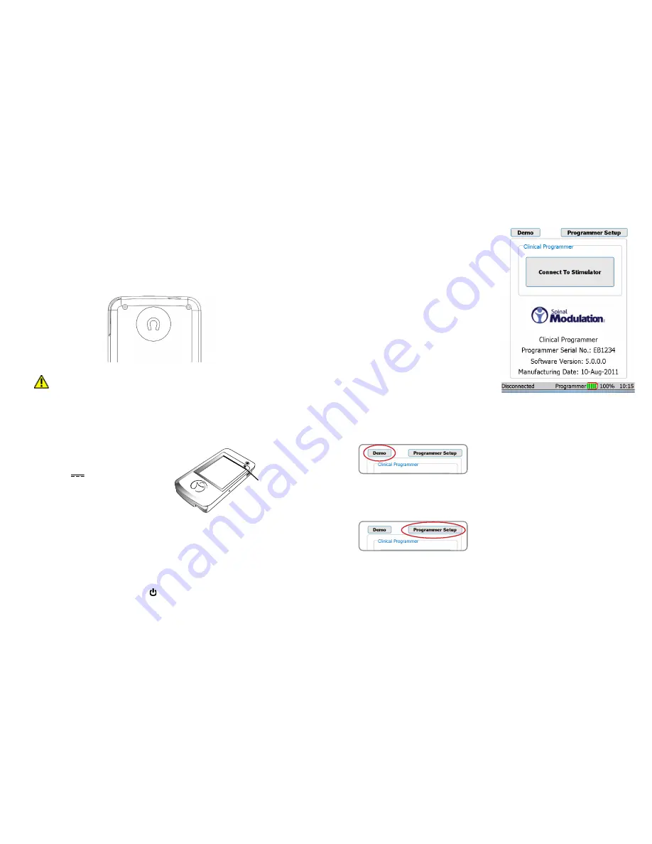
Main Menu

The Main Menu displays three primary functions:

•   

Demo:

 Puts the system into a stand-

alone demo mode allowing you to use 

all programmer functions without it being 

connected to a NS.

•   

Programmer Setup:

 Allows you to set the 

Clinical Programmer date and time, activate 

the FCE Workspace on the Programmer, 

and set and modify the Programmer 

password.

•   

Connect to Stimulator:

 Opens a screen 

that allows you to communicate with the 

NS device.

The Main Menu identifies the device as the Spinal 

Modulation Clinical Programmer. Furthermore, 

Programmer’s Serial Number, Software Version, 

and Manufacturing date are displayed.

At the bottom of the Main Menu, the status bar 

displays the Programmer – NS connection status, 

the battery charge level and the time. 

Refer to the 

section on the Programmer Status Bar in this User 

Manual.

Demo 

Select “Demo” on the Main Menu to initiate Demo mode. 

Buttons will be purple to indicate that the Programmer 

is operating in Demo mode. No NS device is needed for 

this mode —just the Programmer. The Programmer will 

have simulated NS data on it and will simulate the RF 

communication with the NS. This means that at the start of 

every Demo session, the data will always be the same.

Programmer Setup

Select “Programmer Setup” on the Main Menu to get the 

setup screen.

The device is 

charging when 

the amber light 

is on.

Summary of Contents for Clinical Programmer

Page 1: ...thorized duplication or use is prohibited AXIUM SPINALMODULATION and the Man in Circle Design are trademarks and or registered trademarks of Spinal Modulation Inc Clinical Programmer Model MN20700 03 User Manual Authorization to affix the CE mark granted in 2011 ...

Page 2: ... Workspace Navigation 9 Temporary and Permanent Programming 10 More on Editing Text Fields 10 USING THE WORKSPACES 10 Profile Workspace 10 Patient Information Tab Profile Patient 11 Clinic Information Tab Profile Clinic 12 Stimulator Information Tab Profile NS 12 Leads Information Tab Profile Leads 13 System Information Tab Profile System 13 Stim Workspace 14 Stim Tabs Stim Target Name 14 Impedanc...

Page 3: ...ds and stimulator hardware used differ the programmer hardware and instructions for programming the TNS and INS devices are the same NOTE In this manual the general abbreviation NS is used for information which applies to both TNS and INS In all other cases the specific abbreviations TNS or INS are used For specific description of the TNS and INS system components and implant procedures refer to t...

Page 4: ... concern regarding the proper function of the Spinal Modulation NS System please contact your Spinal Modulation representative RF OPERATING FREQUENCIES Nearby equipment emitting strong magnetic fields can interfere with RF communication even if the other equipment complies with CISPR emission requirements The operating characteristics are as follows MICS band 402 405 MHz The effective radiated pow...

Page 5: ...cycles with normal use Connect the Clinical Programmer to the Charger and attach to an outlet regularly to keep it charged Programmer Power Up Turn the Clinical Programmer ON by pressing the button The Main Menu will be displayed NOTE If the Clinical Programmer screen does not turn on follow the instructions for charging the battery and try again Main Menu The Main Menu displays three primary func...

Page 6: ... telemetry connection is cancelled 6 Move the Clinical Programmer magnet over the NS device in a circular motion to connect The indicator status bar on the bottom left of the screen will display Connected if the connection attempt is successful If the Programmer could not communicate with the NS device an error message will appear and Disconnected will be displayed in the status bar NOTE If after ...

Page 7: ...e programmed NS settings NOTE When programming is complete select the Exit button to conserve power Temporary and Permanent Programming Whenever a change is made to a parameter value or other data field while the NS is within telemetry range this value immediately becomes temporarily active The corresponding value or data selection appears in a red bold underlined font NOTE The temporarily active ...

Page 8: ...ng the áü button near the space bar allows the use of accented characters Clinic Information Tab Profile Clinic Enter or modify the physician and clinic information in the text fields provided Physician Name Clinic Name Clinic After Hours Contact Phone Number Clinic Phone Number Clinic Email Clinic Address Stimulator Information Tab Profile NS The NS tab provides a summary of information related t...

Page 9: ...the device switches off or back on delivered therapy Stim Workspace Press the Stim tab to access the Stimulation Settings Workspace The Stimulation Settings Workspace is divided into five tabs which are used to Activate turn on up to four leads Adjust electrode configurations Measure impedance Set nominal values to begin stimulation Perform trial mapping Confirm the response and sensation of speci...

Page 10: ...st be valid prior to activating the lead A valid lead configuration must include at least one positive and one negative electrode Lead Enable must be ON before the amplitude can be increased from 0 µA Location Enter the spinal level where stimulation therapy is delivered by this lead Pulse Parameters To select and change pulse parameters first press the desired increment level Fine Medium Coarse A...

Page 11: ...to the programmed durations when out of session or in session in the Group Workspace this allows the clinician to evaluate and optimize On Off durations When in session in the Stim Workspace Periodic Stimulation will be inactive stimulation will remain ON to allow the clinician to optimize pulse parameters Rework Tabs Utility Rework This screen provides one button automation of the normal TNS rewo...

Page 12: ...tient Programmer s Programmer Setup screen select the desired language then press the Bind Stimulator button Follow the sequence of prompts to enter the target NS serial number and complete the Binding process The Programmer will reboot upon completion Stimulator Unbinding On a bound Patient Programmer press the Unbind Stimulator button to remove the binding This will free the Patient Programmer t...

Page 13: ... of the test level Mains power quality should be that of a typical commercial or home environment Power frequency 50 60 Hz magnetic field IEC 61000 4 8 3 A m Power frequency magnetic fields should be at levels characteristic of a typical location in a typical commercial hospital or home environment Guidance and Manufacturer s Declarations GUIDANCE AND MANUFACTURER S DECLARATION Electromagnetic Emi...

Page 14: ...cy range applies NOTE 2 These guidelines may not apply in all situations Electromagnetic propagation is affected by absorption and reflection from structures objects and people Recommended separation distances between portable and mobile RF communications equipment and the Spinal Modulation Neurostimulation System The Spinal Modulation Neurostimulation System is intended for use in an electromagne...

Page 15: ... L C8 R C8 Magnet Turnoff Time Off 1 s 2 s 3 s 4 s 5 s 6 s 7 s 8 s 9 s 10 s 15 s 20 s 25 s 30 s 40 s 50 s 1 min 70 s 80 s 90 s 100 s 110 s 2 min Ramp Duration 1 s 2 s 3 s 4 s 5 s 6 s 7 s 8 s Appendix II Troubleshooting Pop up Messages Condition Buttons Resolution All stimulation has been turned OFF All stimulation turned off due to data corruption OK Contact your Spinal Modulation Representative C...

Page 16: ...FF Stimulation can be turned off either by the All Stim OFF software button on the INS programmer or the Off switch on the TNS OK Stimulator battery has reached End of Service EOS Stimulation has been turned OFF permanently Battery has reached EOS voltage Stimulation is disabled in order to preserve power for RF communication OK Schedule replacement of the Stimulator Pop up Messages Cont Condition...

Reviews: