v
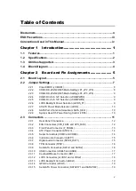
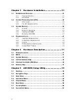
Table of Contents
Conventions Used in This Manual ............................................................... iv
Introduction ............................................. 1
Utilities Supported .............................................................................. 3
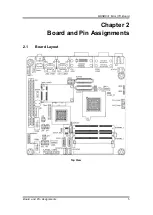
Board and Pin Assignments .................... 5
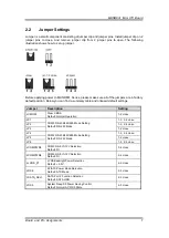
Jumper Settings .................................................................................. 7
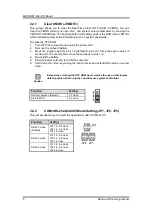
Clear CMOS (JCMOS1) .............................................................................. 8
COM3 RS-232/422/485 Mode Setting (JP1, JP2, JP3) .............................. 8
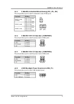
COM4 RS-232/422/485 Mode Setting (JP4, JP5, JP6) .............................. 9
COM3 RI/+5V/+12V Selection (JCOMPWR3) ............................................ 9
COM4 RI/+5V/+12V Selection (JCOMPWR4) ............................................ 9
LVDS Backlight Power Selection (JLVDS_P1) ............................................ 9
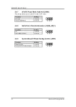
AT/ATX Power Mode Selection (JDS6) ..................................................... 10
SATA Port 2 Function Selection (JSATA_SEL1) ....................................... 10
System Deep S5 Power Saving Control (JDS5) ....................................... 10
FAN Connectors (CPU_FAN1 and SYS_FAN1) ....................................... 12
Front Panel Connector (F_PANEL) ........................................................... 13
ATX Power Connector (ATX12V) .............................................................. 14
Serial Connectors (COM3 and COM4) ..................................................... 14
Internal Audio Connector (AAFP1) ............................................................ 15
Digital Audio Connector (SPDIF_OUT1) ................................................... 15
TPM Connector (TPM1) ............................................................................ 16
Serial ATA Connectors (SATA1 and SATA2) ............................................. 16
USB Connectors (USB45 and USB6) ....................................................... 17
Keyboard/Mouse Connector (KB1) ........................................................... 17
LVDS Connectors (JLVDS1 and JLVDS2) ................................................ 18
LVDS Backlight Connector (JBKL1) .......................................................... 19
GPIO Connector (JDIO1) .......................................................................... 19
Serial ATA Power Connectors (SATAPW1 and SATAPW2) ...................... 19
Summary of Contents for Mano831 Series
Page 1: ...MANO831 Series Intel AtomTM D2550 Mini ITX Motherboard User s Manual ...
Page 10: ...MANO831 Mini ITX Board 4 Introduction 1 4 Block Diagram ...
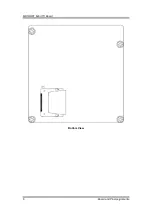
Page 12: ...MANO831 Mini ITX Board 6 Board and Pin Assignments Bottom View ...
Page 26: ...MANO831 Mini ITX Board 20 Board and Pin Assignments This page is intentionally left blank ...
Page 36: ...MANO831 Mini ITX Board 30 Hardware Installation This page is intentionally left blank ...
Page 39: ...MANO831 Mini ITX Board Hardware Description 33 ...
Page 41: ...MANO831 Mini ITX Board Hardware Description 35 ...
Page 42: ...MANO831 Mini ITX Board 36 Hardware Description ...
Page 44: ...MANO831 Mini ITX Board 38 Hardware Description This page is intentionally left blank ...

