MANO831 Mini ITX Board
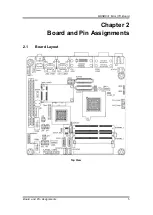
Board and Pin Assignments
7
2.2
Jumper Settings
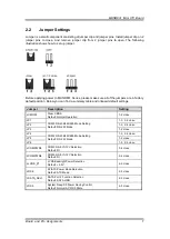
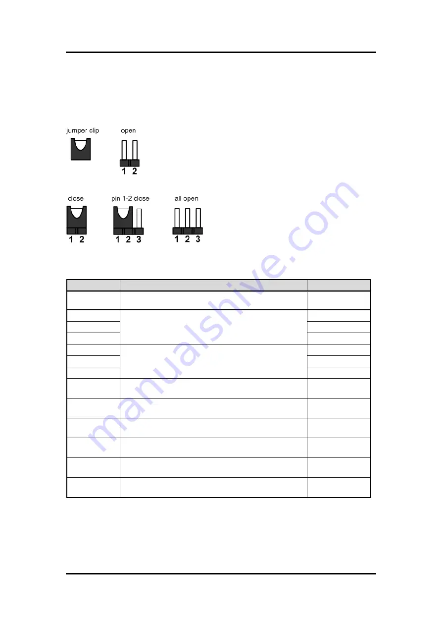
Jumper is a small component consisting of jumper clip and jumper pins. Install jumper clip on 2
jumper pins to close. And remove jumper clip from 2 jumper pins to open. The following
illustration shows how to set up jumper.
Before applying power to MANO831 Series, please make sure all of the jumpers are in factory
default position. Below you can find a summary table and onboard default settings.
Jumper
Description
Setting
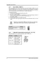
JCMOS1
Clear CMOS
Default: Normal Operation
1-2 close
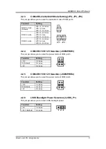
JP1
COM3 RS-232/422/485 Mode Setting
Default: RS-232 Mode
1-3, 2-4 close
JP2
1-3, 2-4 close
JP3
1-2 close
JP4
COM4 RS-232/422/485 Mode Setting
Default: RS-232 Mode
1-3, 2-4 close
JP5
1-2 close
JP6
1-3, 2-4 close
JCOMPWR3
COM3 RI/+5V/+12V Selection
Default: RI
3-4 close
JCOMPWR4
COM4 RI/+5V/+12V Selection
Default: RI
3-4 close
JLVDS_P1
LVDS Backlight Power Selection
Default: +3.3V
2-3 close
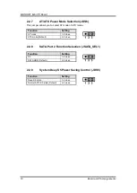
JDS6
AT/ATX Power Mode Selection
Default: ATX Mode
2-3 close
JSATA_SEL1
SATA Port 2 Function Selection
Default: SATA HDD
2-3 close
JDS5
System Deep S5 Power Saving Control
Default: Normal ACPI S5 State
2-3 close
Summary of Contents for Mano831 Series
Page 1: ...MANO831 Series Intel AtomTM D2550 Mini ITX Motherboard User s Manual ...
Page 10: ...MANO831 Mini ITX Board 4 Introduction 1 4 Block Diagram ...
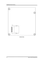
Page 12: ...MANO831 Mini ITX Board 6 Board and Pin Assignments Bottom View ...
Page 26: ...MANO831 Mini ITX Board 20 Board and Pin Assignments This page is intentionally left blank ...
Page 36: ...MANO831 Mini ITX Board 30 Hardware Installation This page is intentionally left blank ...
Page 39: ...MANO831 Mini ITX Board Hardware Description 33 ...
Page 41: ...MANO831 Mini ITX Board Hardware Description 35 ...
Page 42: ...MANO831 Mini ITX Board 36 Hardware Description ...
Page 44: ...MANO831 Mini ITX Board 38 Hardware Description This page is intentionally left blank ...

