MANO831 Mini ITX Board
Board and Pin Assignments
11
2.3
Connectors
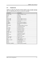
Signals go to other parts of the system through connectors. Loose or improper connection
might cause problems, please make sure all connectors are properly and firmly connected.
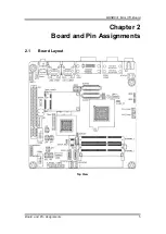
Here is a summary table which shows all connectors on the hardware.
Connector
Description
COM1, COM2
COM1 and COM2 Connector
VGA1
VGA Port
DC1
12V DC IN
DVI
DVI
–D Port
LAN1_USB23
LAN1 and USB 2.0 Connector
LAN2_USB01
LAN2 and USB 2.0 Connector
Audio1
Audio Jack
SODIMM_1
204-pin DDR3 SO-DIMM Slot 1
SODIMM_2
204-pin DDR3 SO-DIMM Slot 2
PCI
PCI Slot
MINI-CARD1
PCI-Express Mini Card Connector
CF1
CompactFlash
TM
Socket
CPU_FAN1
CPU Fan Connector
SYS_FAN1
System Fan Connector
F_PANEL
Front Panel Connector
ATX12V
ATX Power Connector
COM3, COM4
Serial Connectors
AAFP1
Internal Audio Connector
SPDIF_OUT1
Digital Audio Connector
TPM1
TPM Connector
SATA1, SATA2
Serial ATA Connectors
USB45, USB6
USB Connectors
KB1
Keyboard/Mouse Connector
JLVDS1, JLVDS2
LVDS Connectors
JBKL1
LVDS Backlight Connector
JDIO1
GPIO Connector
SATAPW1, SATAPW2
Serial ATA Power Connectors
Summary of Contents for Mano831 Series
Page 1: ...MANO831 Series Intel AtomTM D2550 Mini ITX Motherboard User s Manual ...
Page 10: ...MANO831 Mini ITX Board 4 Introduction 1 4 Block Diagram ...
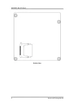
Page 12: ...MANO831 Mini ITX Board 6 Board and Pin Assignments Bottom View ...
Page 26: ...MANO831 Mini ITX Board 20 Board and Pin Assignments This page is intentionally left blank ...
Page 36: ...MANO831 Mini ITX Board 30 Hardware Installation This page is intentionally left blank ...
Page 39: ...MANO831 Mini ITX Board Hardware Description 33 ...
Page 41: ...MANO831 Mini ITX Board Hardware Description 35 ...
Page 42: ...MANO831 Mini ITX Board 36 Hardware Description ...
Page 44: ...MANO831 Mini ITX Board 38 Hardware Description This page is intentionally left blank ...

