eBOX640-521-FL Series U
ser’s Manual
Jumper & Connector Settings
20
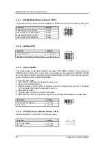
3.2.1 COM2 Data/Power Select (JP1)
The COM2 port has +5V level power capability on DCD# and +12V level on RI# by setting JP1.
3.2.2 Audio(JP2)
3.2.3 Clear CMOS
This jumper allows you to clear the Real Time Clock (RTC) RAM in CMOS. You can clear the
CMOS memory of date, time, and system setup parameters by erasing the CMOS RTC RAM
data. The onboard button cell battery powers the RAM data in CMOS, which includes system
setup information such as system passwords.
To erase the RTC RAM:
1. Turn OFF the computer and unplug the power cord.
2. Remove the onboard battery.
3. Move the jumper clip from pins 1-2 (default) to pins 2-3. Keep the clip on pins 2-3 for about
5~10 seconds, then move the clip back to pins 1-2.
4. Re-install the battery.
5. Plug the power cord and turn ON the computer.
6. Hold down the <Del> key during the boot process and enter BIOS setup to re-enter data.
3.2.4 AT/ATX Power Mode Select (JP6)
Use this Quick-SW to select AT or ATX power mode.
Functions
Settings
Power: Set CN27 pin 1 to +5V level
1-3 close
Data: Set CN27 pin 1 to DCD# (Default)
3-5 close
Power: Set CN27 pin 8 to +12V level
2-4 close
Data: Set CN27 pin 8 to RI# (Default)
4-6 close
Function
Setting
Line-out (Default)
1-3, 2-4 close
Speaker out (non-used for internal-CNN)
3-5, 4-6 close
Function
Setting
Normal operation (Default)
1-2 close
Clear CMOS
2-3 close
Function
Setting
ATX mode (Default)
1-2 close
AT mode
2-3 close
Summary of Contents for eBOX640-521-FL Series
Page 1: ...eBOX640 521 FL Series Embedded System User s Manual ...
Page 13: ...eBOX640 521 FL Series User s Manual Introduction 5 1 3 2 Wall mount Bracket Dimensions ...
Page 43: ...eBOX640 521 FL Series User s Manual BIOS Setup Utility 35 ...
Page 62: ...eBOX640 521 FL Series User s Manual 54 Watchdog Timer This page is intentionally left blank ...
Page 71: ...eBOX640 521 FL Series User s Manual TPM Settings 63 ...


