eBOX640-521-FL Series U
ser’s Manual
Introduction
7
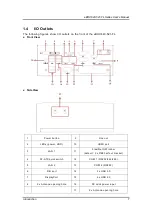
The following figures show I/O outlets on the front of the eBOX640-521-FL.
Front View
Side View
1
Power button
9
Line out
2
LEDs (power, HDD)
10
HDMI port
3
LAN 1
11
Flexible IO W indow
(default : 2 x DB9 half cut bracket)
4
AT-ATX quick switch
12
COM 1 (RS232/422/485)
5
LAN 2
13
COM 2 (RS232)
6
DIO port
14
2 x USB 3.0
7
DisplayPort
15
4 x USB 2.0
8
2 x Antenna opening hole
16
DC Jack power input
17
2 x Antenna opening hole
Summary of Contents for eBOX640-521-FL Series
Page 1: ...eBOX640 521 FL Series Embedded System User s Manual ...
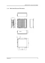
Page 13: ...eBOX640 521 FL Series User s Manual Introduction 5 1 3 2 Wall mount Bracket Dimensions ...
Page 43: ...eBOX640 521 FL Series User s Manual BIOS Setup Utility 35 ...
Page 62: ...eBOX640 521 FL Series User s Manual 54 Watchdog Timer This page is intentionally left blank ...
Page 71: ...eBOX640 521 FL Series User s Manual TPM Settings 63 ...


