eBOX640-521-FL Series U
ser’s Manual
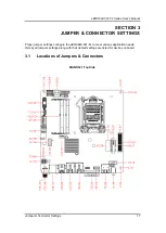
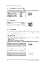
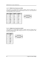
Jumper & Connector Settings
19
3.2
Summary of Jumper Settings
Proper jumper settings configure the eBOX640-521-FL to meet various application purposes.
A table of all jumpers and their default settings is listed below.
MANO521
Jumpers
Descriptions
Settings
JP1
COM2 Data/Power Select
Default: RS-232 Data
CN27 Pin 1: DCD#
3-5 Close
CN27 Pin 8: RI#
4-6 Close
JP2
Audio Output Select
(Line-out only)
1-3,2-4 Close
JP4
Clear CMOS
Default: Normal Operation
1-2 Close
JP5
Case Open Select
Default: Close
1-2 Close
JP6
AT/ATX Power Mode for Quick-SW-Cable Select
Default: ATX Mode
1-2 Close
【
Note
】
How to setup Jumpers
That a cap on a jumper is to
“close” the jumper, whereas that off a jumper is to “open” the
jumper.
[Open] [Closed] [Pin1 -2 Closed]
Summary of Contents for eBOX640-521-FL Series
Page 1: ...eBOX640 521 FL Series Embedded System User s Manual ...
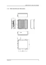
Page 13: ...eBOX640 521 FL Series User s Manual Introduction 5 1 3 2 Wall mount Bracket Dimensions ...
Page 43: ...eBOX640 521 FL Series User s Manual BIOS Setup Utility 35 ...
Page 62: ...eBOX640 521 FL Series User s Manual 54 Watchdog Timer This page is intentionally left blank ...
Page 71: ...eBOX640 521 FL Series User s Manual TPM Settings 63 ...

