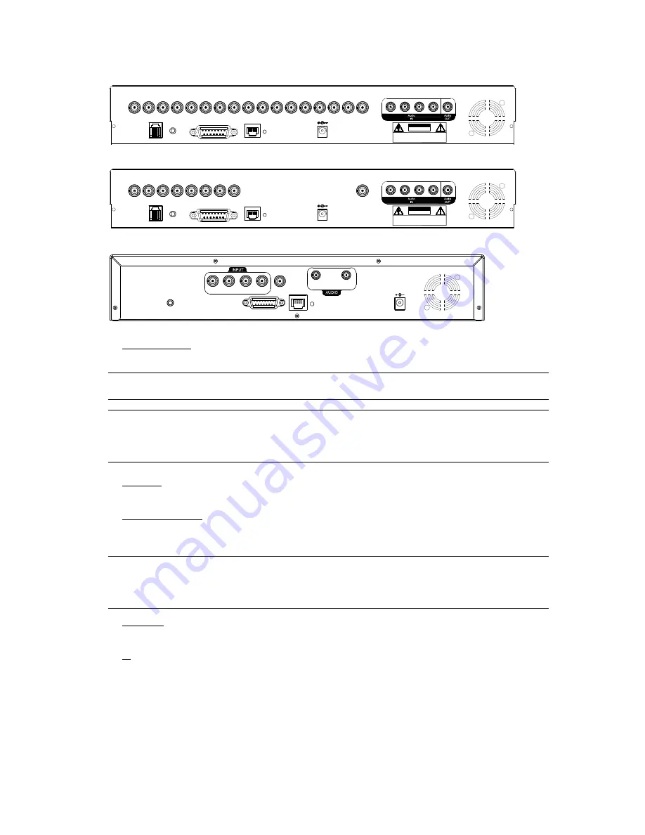
background image


-5-


2.3 Rear Panels 


16CH (The fan is optional) 

RI S K OF EL ECTRI C S HO CK

    DO NOT OPEN

DC 19V

WARNING

: TO REDUCE THE RISK O F ELE CTRIC SHOCK,

DO NO T REMOV E COVER (OR BACK).

NO USE R-SERVICEABLE P ARTS INSIDE.

REFER SERVICING TO QUALIFIED

SERVICE PERSONNEL.

ACT.

LINK

LAN

EXTERNAL I/O

IR

RS485

1

4

2

3

5

6

7

8

9

10

11

12

13

14

15

16

MONITOR

1

2

3

4

1


8CH (The fan is optional) 

RI S K OF EL ECTRI C S HO CK

    DO NOT OPEN

DC 19V

WARNING

: TO REDUCE THE RISK O F ELE CTRIC SHOCK,

DO NO T REMOV E COVER (OR BACK).

NO USE R-SERVICEABLE P ARTS INSIDE.

REFER SERVICING TO QUALIFIED

SERVICE PERSONNEL.

ACT.

LINK

LAN

EXTERNAL I/O

IR

RS485

1

4

2

3

5

6

7

8

MONITOR

1

2

3

4

1


4CH (The fan is optional) 

EX TERN AL I/ O

LAN

LINK

ACT.

MO NITOR

DC 19V

OUT

IN

1

2

3

4

IR


1)  INPUT (1 ~ 16CH) 

Connect to video sources, such as cameras. 

Note:

  The  DVR  will  automatically  detect  the  video  system  of  the  camera,  please  make  sure  that  the 

cameras are properly connected to the DVR and power-supplied before the DVR is turned on. 


Note:

 If you want to make a video backup with audio, please connect audio cameras to the channels 

which support the audio function. 

For 16CH & 8CH DVR, the audio channels are CH1, CH2, CH3 and CH4. 

For 4CH DVR, the audio channel is CH1. 

2)  MONITOR 

Connect to a CRT monitor for video output. 

3)  Audio IN (1 / 2 / 3 / 4) 

Connect to audio sources, such as cameras equipped with the audio function. 

When users start recording, the audio input will also be recorded with corresponding video channel. 

Note: 

The audio source connected to the “Audio 1” will be recorded with the video of the “CH1”. 

The audio source connected to the “Audio 2” will be recorded with the video of the “CH2”. 

The audio source connected to the “Audio 3” will be recorded with the video of the “CH3”. 

The audio source connected to the “Audio 4” will be recorded with the video of the “CH4”.


4)  Audio OUT 

Connect to a monitor or speaker with 1 mono audio output. 

5)  IR 

Connect the IR receiver extension line for remote control. 

Summary of Contents for KPD604

Page 1: ...s of the European law on the Restriction of Hazardous Substances RoHS directive which means our manufacture processes and products are strictly lead free and without the hazardous substances cited in...

Page 2: ...sed software AP disc DSUB PIN connector Manual quick start IR remote control manual AAA size battery 2 Vertical panel sticker for remote controller certain models only Note Before using the IR remote...

Page 3: ...sub layer of the advanced setting menu press this button to confirm the settings and go back to the upper layer 6 LIVE Press this button to stop the playback and return to the live mode 7 Channel Disp...

Page 4: ...nnel Icon means Playback audio of the 2nd audio channel Icon means Live audio of the 3rd audio channel Icon means Playback audio of the 3rd audio channel Icon means Live audio of the 4th audio channel...

Page 5: ...ideo 18 STOP Press this button to stop playback and return to the live mode 19 SLOW Under the playback mode press this button to slowly playback the recorded file by 1 4 speed or 1 8 speed 20 Under th...

Page 6: ...that the cameras are properly connected to the DVR and power supplied before the DVR is turned on Note If you want to make a video backup with audio please connect audio cameras to the channels which...

Page 7: ...etc For detailed I O port PIN configuration please refer to APPENDIX 1 PIN CONFIGURATION in the user s manual 7 LAN Connect to Internet by LAN cable 8 LINK ACT When your DVR is connected to the Intern...

Page 8: ...se Step 7 Connect the HDD to the power connector and IDE BUS make sure to align the HDD precisely for pin connection Make sure the HDD mode is set to Master or Slave as indicated below for the IDE BUS...

Page 9: ...ON EVENT STATUS ON IMAGE SIZE CIF QUALITY BEST IMAGE PER SECOND 120 RECORD TIMER OFF DETECTION TIMER OFF DATE 2007 AUG 08 21 30 00 FORMAT Y M D DAYLIGHT SAVING OFF ADVANCE SELECT BACK NEXT ENTER 3 5 P...

Page 10: ...connections and setup a surveillance system is established and you can experience the marvelous and useful functions of this DVR The diagram below illustrates all the available connections of this DV...

Page 11: ...s recording without notice 1 Continuous Recording Icon When the DVR is properly connected with camera you can see the icon recording on the screen 2 Event Recording Icon When the motion alarm detectio...

Page 12: ...monitoring mode 4 Slow Playback Press SLOW button to get 1 4X speed playback and press twice to get 1 8X speed playback 5 Audio Playback Use these two buttons to select the live or playback sound of...

Page 13: ...to upgrade Step 5 Press Update Firmware or Update Language button to start the upgrade 4 6 Search 1 Search by List Press LIST button on the DVR control panel to show the list for all types of the reco...

Page 14: ...ew change the settings of the quick start menu items MENU Enter exit the quick start menu Make the selection Change the setting Go to the upper layer or sub layer Make the selection ENTER Confirm the...

Reviews: