


4
2. CONNECTION AND SETUP
Note:
The DVR is designed to automatically detect the video system of the connected cameras (NTSC or
PAL). To make sure the system detection is correct, please check if the cameras are connected to
the DVR and power-supplied before the DVR is powered on.
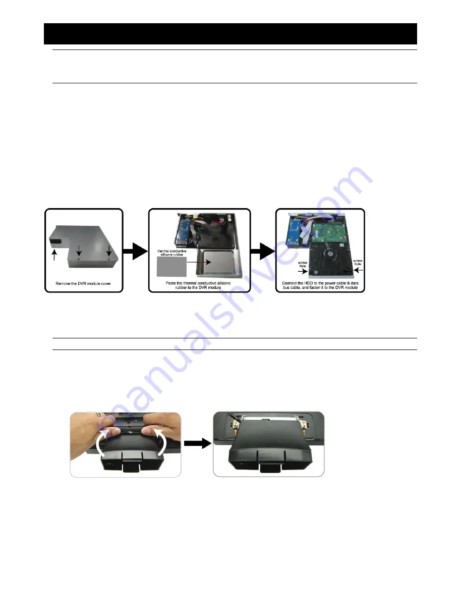
2.1 Install HDD
One SATA HDD should be installed in the DVR module, and it must be purchased separately.
Step 1: Loose the screws on the upper cover and remove it.
Step 2: Find the thermal conductive silicone rubber in the accessory pack, and paste it to the protrusive surface on
the module.
Step 3: With the PCB side facing up, connect the compatible SATA HDD to the data bus and power, and place it in
the module.
Step 4: Find the two screw holes on the module, and fasten the HDD to the module with the supplied screws, one
for each side.
Step 5: Close the upper cover of the module, and fasten all the screws you loosened in Step 1.
2.2 Install DVR Module to LCD Monitor
After the HDD is installed in the DVR module, place the module to the LCD monitor.
Note:
The illustration below is taking Model 2 as an example.
1. Place the monitor face-down on a soft, protected surface.
2. Check if the LCD monitor base is fixed to the monitor.
If no, please skip to the next step; if yes, remove the LCD monitor base as indicated below:
a) First, snap off the screw cover from the monitor base.
b) Remove the four stand screws.
3. A slot on the rear panel of the LCD monitor is reserved for the DVR module. Find the slot and remove the slot
cover.
4. Slide the DVR module to the slot as indicated below.
5. Push the module to the end, and fix it with the supplied screws.
6. Connect the VGA cable on the LCD monitor to the VGA port on the DVR module.
Summary of Contents for AVL683
Page 26: ...23...


