


1
1. KNOWING YOUR LCD DVR
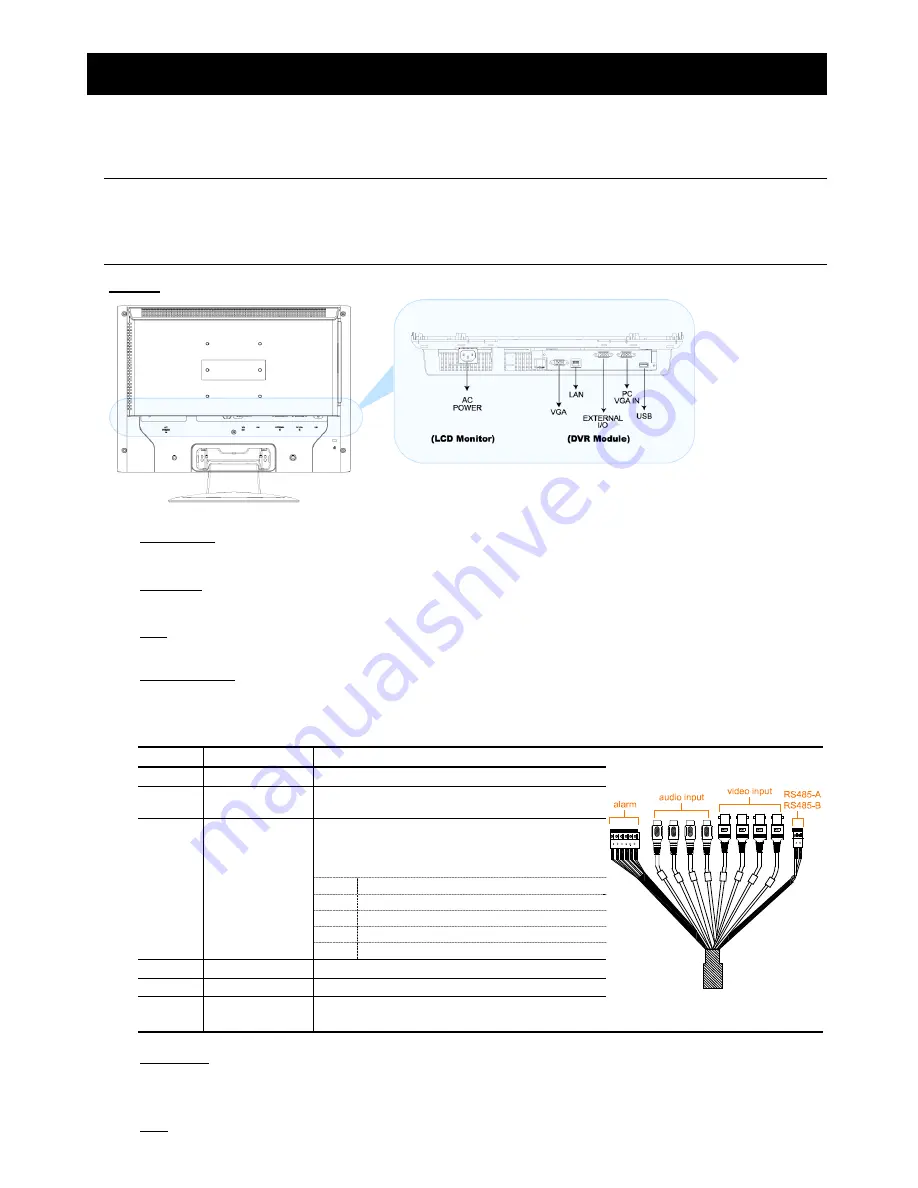
1.1 Rear Panel
Below shows the illustration when the DVR module is installed in the LCD monitor (view from bottom to top).
Note:
For how to install the DVR module to the LCD monitor, please refer to “2.2 Install DVR Module to
LCD Monitor” at page 4.
For how to remove the DVR module from the LCD monitor, please refer to “APPENDIX 4 DVR
MODULE REMOVAL” at page 33.
‧
Model 1
1) AC
POWER
Connect to power with the supplied LCD monitor power cable.
2) VGA
OUT
Connect the monitor directly to this jack on the DVR module.
3) LAN
Connect to network with a network cable.
4) EXTERNAL
I/O
Connect the supplied external I/O cable for video, audio, alarm, and external device (such as PTZ camera)
connection.
Each connector is labeled as follows:
Label Meaning
Description
V1 ~ V4
Video Input 1 ~ 4
Connect to video sources, such as cameras.
A1 ~ A4
Audio Input 1 ~ 4
Connect to audio sources, such as cameras
equipped with the audio function.
Connect alarm input (1~4) and GND connector with
wires. Once an alarm is triggered, the DVR will start
recording the corresponding channel, and the buzzer
will be on.
Label Corresponding Channel…
1 Channel
1
2 Channel
2
3 Channel
3
1 ~ 4
Alarm:
Alarm Input 1 ~ 4
4 Channel
4
G Alarm:
GND
Ground
O Alarm:
Output
A & B
RS485-A
RS485-B
Used to connect to a PTZ camera, keyboard
controller, or other compatible external device.
5) PC VGA IN
Connect the DVR module and your PC with an additional monitor video cable to switch the display between the
DVR and PC.
6) USB
To quickly backup or upgrade firmware/OSD, you can insert a compatible USB flash drive into this USB port.
Summary of Contents for AVL683
Page 26: ...23...


