background image

CONNECTION AND SETUP 

4


2. CONNECTION AND SETUP 

Before the DVR is powered on, make sure you have installed a hard disk and connected at least one camera. For 
details, please refer to the following sections. 

Note: 

The DVR is designed to automatically detect the video system of the connected cameras (NTSC or 
PAL). To make sure the system detection is correct, please check if the cameras are connected to 
the DVR and power-supplied before the DVR is powered on. 


2.1 SATA HDD Installation 

A SATA HDD must be installed before the DVR is powered on. 

Note: 

It’s recommended to clear all data in the hard disk when the DVR is powered on and the date & 
time are set correctly to ensure the recorded data are not mixed with other data previously saved 
in the same hard disk. For details, please refer to “2.5 Clear Hard Disk” at page 8.


For AVC799B & AVC797B 

Step1: Loose the screws on the upper cover and open the upper cover of the DVR. 

Note:

  The DVR cover is made of metal. Please be careful with its edge when you remove the cover.


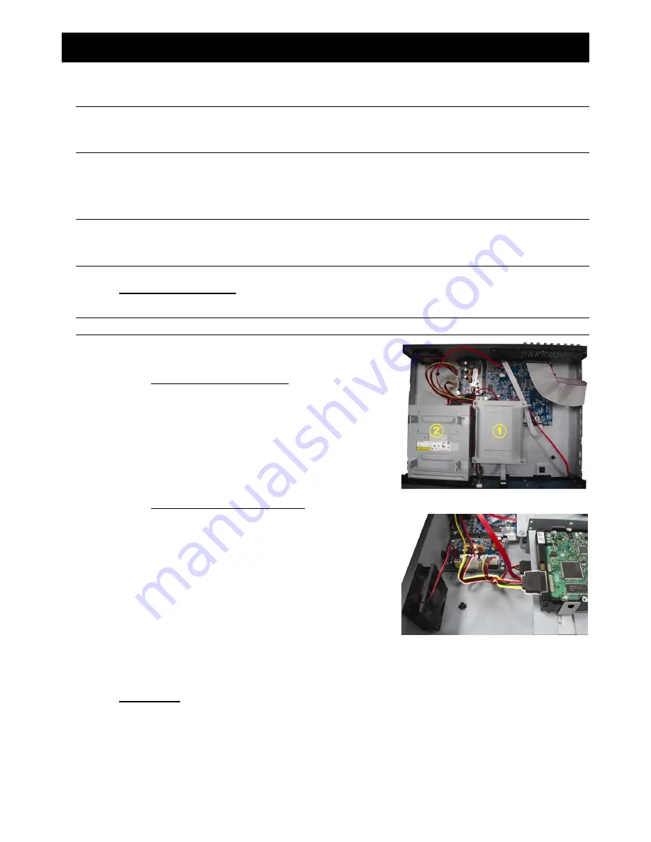
Step2: There are two HDD brackets for this DVR as indicated on 

the right picture. 
2-1 To install on the first bracket 
Remove the bracket, and align the screw holes of the 
bracket with the HDD’s screw holes. Make sure the 
PCB side of the HDD is facing up.   

Fasten the HDD to the bracket, and connect the power 
connector and data bus connector to the HDD. Then, 
replace the bracket to DVR. 

2-2 To install on the second bracket 
Connect the power connector and data bus connector 
to the HDD.   

When connecting the power cable, make sure the cable 
is passed through the power cable of DVD writer. This is 
to prevent the HDD power cable from interfering with 
the fan spinning. 

Align the screw holes of the bracket with the HDD’s 
screw holes. Make sure the PCB side of the HDD is 
facing up. Then, fasten the HDD to the bracket. 

Step3: Close the upper cover of the DVR, and fasten all the screws you loosened in Step1. 


For AVC794B 

Step1: Remove the screws on the top cover of DVR, and remove the top cover. 
Step2: Remove the HDD bracket. Then, with the PCB side facing up, connect the compatible HDD to the 

power connector and data bus connector.   

Step3: Put the compatible HDD in the bracket, and fasten it with the supplied screws, two for each side. 
Step4: Replace the bracket back to the DVR. 

Summary of Contents for AVC794B

Page 1: ...er Manual Intelligent Video Surveillance GUI Display with USB Mouse Control Please read instructions thoroughly before operation and retain it for future reference For the actual display operation ple...

Page 2: ...ch In Motion Limited and are registered and or used in the U S and countries around the world Used under license from Research In Motion Limited Android is a trademark of Google Inc Use of this tradem...

Page 3: ...ject to the copyright of the corresponding author Further source codes which are subject to the GPL licenses are available upon request We are pleased to provide our modifications to the Linux Kernel...

Page 4: ...B Mouse 9 3 2 Quick Menu Bar 9 3 2 1 Channel Switch 9 3 2 2 PTZ Control Panel 10 3 3 Main Menu 10 4 BASIC OPERATION 11 4 1 Live Page 11 4 2 Record Icon 11 4 3 Playback 11 4 3 1 Playback Control 12 4 3...

Page 5: ...EMOTE OPERATION 35 6 1 Supplied Licensed Software 35 6 1 1 Installation Network Connection 35 6 1 2 Control Panel Overview 36 6 1 3 General Operation 38 6 1 4 E Map 40 6 2 Web Browser 46 6 2 1 Event P...

Page 6: ...channel is displayed it will repeat from CH1 again To exit this mode press SEQ again 5 SLOW In the playback mode press to show slow playback 6 ZOOM Press to enlarge the picture of selected channel in...

Page 7: ...tor of a camera VIDEO LOOP 1 16 1 8 Video output connector Note The DVR will automatically detect the video system of the camera please make sure that the cameras are properly connected to the DVR and...

Page 8: ...te control 9 EXTERNAL I O This port is used to connect external devices such as speed dome cameras or external alarm etc 10 LAN Connect to Internet by LAN cable 11 DC 19V Connect to the supplied adapt...

Page 9: ...rackets for this DVR as indicated on the right picture 2 1 To install on the first bracket Remove the bracket and align the screw holes of the bracket with the HDD s screw holes Make sure the PCB side...

Page 10: ...io input Optional Connect the camera audio output to the DVR audio input port with a coaxial cable or RCA cable with BNC connectors 3 Connecting to power Connect the camera with indicated power supply...

Page 11: ...sulating coating of the RJ11 cable Remove one end of the insulating coating of the RJ11 cable to find the RS485 A and the RS485 B wires and remove the insulating coating to reveal the naked wires for...

Page 12: ...time of your DVR after the recording function is activated Otherwise the recorded data will be disordered and you will not be able to find the recorded file to backup by time search If users change th...

Page 13: ...SYSTEM TOOLS BAUD RATE 2400 SYSTEM INFO HOST ID 000 USB BACKUP R E T R 5 DVD BACKUP AUTO KEY LOCK NEVER CLEAR HDD HDD 0 RESET DEFAULT SUBMIT REMOTE CONTROL ID 000 SERIAL TYPE RS485 VIDEO FORMAT NTSC...

Page 14: ...p or click to enter the search list For details please refer to 4 3 Playback at page 11 Switch to the channel you want first and click to enter the zoom in mode In this mode click and drag the red fra...

Page 15: ...ction Before using it you need to assign a specific function that will be enabled when AUTO is clicked For details please refer to the user manual of the PTZ camera Preset point Click to enter the PTZ...

Page 16: ...vent Human detection event Flow counting enabled Smart zoom Record mode Frame Record mode Field Record mode CIF 4 2 Record Icon 1 Manual Recording By defaults manual recording is on when the DVR is po...

Page 17: ...video clip recorded during this whole hour Repeat Click to set point A and point B in a video clip and the system will play only the specified range in that clip Backup Click to open the backup menu f...

Page 18: ...ED CONFIG CAMERA DE INTERLACE For AVC799B 797B Only OFF DETECTION FULL SCREEN DURATION 03 ALERT QUAD SCREEN DURATION For AVC799B 797B Only 03 NETWORK DWELL SCREEN DURATION 03 DISPLAY DISPLAY COVERT ON...

Page 19: ...A DETECTION ALERT NETWORK DISPLAY RECORD DEVICES DCCS IVS NOTIFY SCHEDULE SETTING Click to set record timer and detection timer 5 1 QUICK START 5 1 1 GENERAL QUICK START GENERAL CHANNEL TITLE ON TIME...

Page 20: ...individually for each channel QUICK START MANUAL EVENT TIMER CHANNEL IMAGE SIZE I P S QUALITY CH1 CIF 25 SUPER BEST CH2 CIF 25 SUPER BEST CH3 CIF 6 HIGH CH4 FIELD 25 SUPER BEST AVAILABLE IPS CIF 69 F...

Page 21: ...O DAYLIGHT SAVING OFF DAYLIGHT START TIME 1ST MON AUG 06 00 END TIME LAST MON OCT 10 00 ADJUST 01 00 EXIT Depending on the time zone you re in 1 DAYLIGHT SAVING Select to enable ON or disable OFF this...

Page 22: ...RIVE LIST at page 57 Note After upgrading firmware it s recommended to clear all HDD data for the system to work more stably Before clearing all HDD data please remember to make video backup 5 BACKUP...

Page 23: ...re is used to identify the DVR the remote controller is going to control Please also read the user manual of the IR remote controller for details 8 SERIAL TYPE Here shows the serial type of the DVR RS...

Page 24: ...T INFORMATION 5 4 1 QUICK SEARCH EVENT INFORMATION QUICK SEARCH HARD DISK ALL HDD EVENT SEARCH CHANNEL 01 02 03 04 HDD INFO 05 06 07 08 EVENT LOG 09 10 11 12 13 14 15 16 W 2009 X NOV SUN MON TUE WED T...

Page 25: ...ch MOTION ALARM HUMAN DETECTION INFLOW OUTFLOW VIRTUAL FENCE ONE WAY PASS SCENE CHANGE 5 SEARCH Click START to start search and play the video data immediately 5 4 3 HDD INFO You can check the remaini...

Page 26: ...function is disabled no manual event or timer recording will be activated even if any of these three record functions is set to ON 4 CHANNEL TITLE Click EDIT to input the channel title up to six chara...

Page 27: ...the area under detection 5 5 3 ALERT ADVANCED CONFIG CANERA EXT ALERT ON DETECTION INT BUZZER OFF ALERT KEY BUZZER ON NETWORK VLOSS BUZZER ON DISPLAY MOTION BUZZER ON RECORD ALARM BUZZER ON DEVICES H...

Page 28: ...ECTION NETWORK TYPE STATIC ALERT IP 192 168 001 010 NETWORK GATEWAY 192 168 001 254 DISPLAY NETMASK 255 255 255 000 RECORD PRIMARY DNS 168 095 001 001 DEVICES SECONDARY DNS 139 175 055 244 DCCS PORT 0...

Page 29: ...rs a html file including a link will be sent to the specified FTP site Click the link to access to this DVR and check the event recording ADVANCED CONFIG CANERA NETWORK SNTP FTP E MAIL DETECTION FTP A...

Page 30: ...CED CONFIG CAMERA DE INTERLACE For AVC799B AVC797B Only OFF DETECTION FULL SCREEN DURATION 03 ALERT QUAD SCREEN DURATION For AVC799B AVC797B Only 03 NETWORK DWELL SCREEN DURATION 03 DISPLAY DISPLAY CO...

Page 31: ...able to find the recorded file to backup by time search If users change the date or time accidentally when the recording function is activated it s recommended to clear all HDD data and start recordin...

Page 32: ...ct it automatically and display its model number here To configure the parameters for a zoom lens control camera please refer to 5 5 9 DCCS at page 28 Different zoom lens control cameras might have di...

Page 33: ...f the camera 4 CONNECTION Here shows the examining result for DCCS signal transmission between the DVR and camera The message is as follows MESSAGE SHOWN MEANING CHECKING The DVR is checking the DCCS...

Page 34: ...gered ONE WAY A virtual detection line is set to detect intruders from the specified direction and an alarm will be triggered 3 DISPLAY LINE Select to display the detection line for IVS on the screen...

Page 35: ...ng and return to the live view The IVS icon will be shown on the status bar Click it to show the flow counting panel as follows When anyone walks across the detection line the system will determine hi...

Page 36: ...ng REVERSE Step2 Finish the IVS setting and return to the live view When anyone walks across the detection line the system will determine his movement is in or out and VIRTUAL FENCE An event happens f...

Page 37: ...ou want to search and click SUBMIT in STATISTIC to show the event statistics by DAY in LIST default or CHART To check the statistics in the bar chart click CHART To switch to the MONTH or YEAR view cl...

Page 38: ...1 GUARD Select to enable or disable Push Notification function ON OFF Select to activate the Push Notification function ON OFF Or it could also be activated later from iPhone Note For details about DV...

Page 39: ...22 24 ALARM SUN MON TUE WED THU FRI SAT EXIT X axis 0 24 hours Each time bar is 30 minutes Y axis Monday Sunday 5 6 3 ALARM Select ON to enable alarm timer and select the day and time for this functi...

Page 40: ...the installation When the installation is completed a shortcut icon will be placed on your PC desktop 2 Network Connection L Lo oc ca al l C Co on nn ne ec ct ti io on n v vi ia a L LA AN N LAN is us...

Page 41: ...ide of the control panel b Click to key in the IP address user name password and port number of the DVR you intend to connect OR Click to search the available IP address es of other DVR s under the sa...

Page 42: ...tting Click to choose the language of this program The language change will take effect when this program is closed and executed again Log Click to view all event and recording logs search the desired...

Page 43: ...click or on the main control panel to start the manual recording immediately and the recordings will be saved in the specified location If Motion and or Alarm are checked the recording function will a...

Page 44: ...er Channel within which have the video data you need Download by Time Specify the time range within which has the video data you want in the Start Time and End Time columns Download by Event Select an...

Page 45: ...VR for function scalability Note Before using this function make sure you have the correct upgrade files provided by your installer or distributor Step1 Click and select the IP address of your device...

Page 46: ...In the simplified version click to switch the control panel to the full function version and click to enter the E Map page as follows Note To know where the buttons are please refer to Simplified Vers...

Page 47: ...REMOTE OPERATION 42 STEP3 When the E Map group is created you will see the tree on the top left panel showing all the devices you ve added to this group...

Page 48: ...to catch your attention To know what s happening quickly double click the device icon on the E Map to show the live view How to Edit Remove an Existing E Map Group For Google E Map Group Right click o...

Page 49: ...t click on the group name to show the shortcut menu list and select Edit E MAP or Remove E MAP as needed For Building E Map Group Right click on the group name to show the shortcut menu list and selec...

Page 50: ...REMOTE OPERATION 45 To edit or remove a certain level of the building E Map group right click on the level name and select Edit E MAP or Remove E MAP as needed...

Page 51: ...live view of the DVR Click to enter the playback panel where you can search or select the event you want to play and download to your PC simultaneously For details please refer to 6 2 1 Event Playback...

Page 52: ...display button Click to show 4 cut 9 cut 16 cut display Playback Control Increase the speed for fast rewind Click once to get 4X speed rewind and click twice to get 8X speed etc and the maximum speed...

Page 53: ...Click once to get 4X speed forward and click twice to get 8X speed etc and the maximum speed is 16X Play Click to play the current video clip Pause Click to pause the video playback Stop Click to sto...

Page 54: ...REMOTE OPERATION 49 6 2 2 IVS Statistics...

Page 55: ...ER BEST BEST HIGH NORMAL Hard Disk Storage Accommodates 2 SATA HDDs 1 HDD capacity up to 2TB Quick Search Time Motion Alarm search mode SATA Interface Built in Recording Mode Manual Timer Motion Alarm...

Page 56: ...letters Video Adjustable Hue Saturation Contrast Brightness Date Display Format YY MM DD DD MM YY MM DD YY Daylight Saving YES Power Source 10 DC 19V Power Consumption 10 64 W Operating Temperature 10...

Page 57: ...rol YES Motion Detection Area 16 12 grids per camera for all channels Motion Detection Sensitivity 3 adjustable parameters for accurate detection Pre alarm Recording YES Backup Device USB 2 0 flash dr...

Page 58: ...19V Power Consumption 10 42 W Operating Temperature 10 40 50 104 Dimensions mm 343 W 59 H 223 D System Recovery System auto recovery after power failure Optional Peripherals Keyboard controller The sp...

Page 59: ...PIN 6 9 CH9 PIN 7 11 CH11 PIN 8 13 CH13 PIN 9 15 CH15 10 11 PIN OFF NA 12 RS485 A 13 EXTERNAL ALARM NO Under the normal operation COM disconnects with NO But when any alarm is triggered COM connects...

Page 60: ...2 1 CH1 PIN 3 3 CH3 PIN 4 5 CH5 PIN 5 7 CH7 6 11 PIN OFF NA 12 RS485 A 13 EXTERNAL ALARM NO Under the normal operation COM disconnects with NO But when any alarm is triggered COM connects with NO Atte...

Page 61: ...wires Once an alarm is triggered the DVR will start recording and the buzzer will be on PIN Alarm Corresponding video channel PIN 1 1 CH1 PIN 2 2 CH2 PIN 3 3 CH3 PIN 4 4 CH4 5 GND GROUND 6 EXTERNAL AL...

Page 62: ...se your PC to format the USB flash drive as FAT32 Note You can backup up to 2GB video data for one time USB backup To backup more data please set the time channel s you want and start USB backup again...

Page 63: ...528AS 1TB 7200 rpm ST31000525SV 1TB 7200 rpm ST315000341AS 1 5TB 7200 rpm Seagate ST32000542AS 2TB 7200 rpm WD3200AAKS 320GB 7200 rpm WD5000AACS 500GB 7200 rpm WD6400AAKS 640GB 7200 rpm WD7500AAKS 750...

Page 64: ...TYPE VIDEO FORMAT VERSION USB BACKUP EVENT INFORMATION QUICK SEARCH EVENT SEARCH HDD INFO EVENT LOG ADVANCED CONFIG CAMERA BRIGHTNESS CONTRAST SATURATION HUE COV REC CHANNEL TITLE DETECTION LS SS TS...

Page 65: ...RECORD OVERWRITE EVENT RECORD ALL CHANNEL KEEP DATA LIMIT DAYS RECORD CONFIGURATION DEVICES DCCS IVS CAMERA For AVC799B 797B Only IVS MODE DISPLAY LINE SENSITIVITY RESET COUNT VIRTUAL FENCE AREA SCEN...

Page 66: ...he lithium battery CR2032 is a non chargeable battery and should be purchased separately Please replace only with the same or equivalent type battery in case of danger Step1 Stop all DVR recording imm...

Reviews: