- 14 -
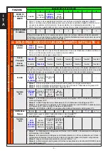
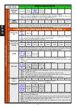
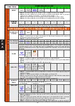
FUNCTIONS
NUMBER OF GREEN LED IMPULSES
1
2
3
4
5
6
7
8
NUMBER OF RED LED IMPULSES
1
OPERATING
MODE
Extension
Extension
(no info Sat)
SERIAL
SIREN
(XTREAM)
Serial Siren
High Speed
•
Value 1: the siren is managed by the central like a extension connected in RS485
•
Value 2: the siren is managed by the central like a extension connected in RS485, but there is no
information of “tamper satellite No. xx and low battery Satellite No. xx
•
Value 3: the siren is managed by control panel as RS485 siren (look at dedicated programming steps)
2
SIREN
ADDRESS
1
2
3
4
5
6
7
8
Bear in mind that there cannot be more key blocks with the same address, otherwise they will stop working
and the control panel will activate a Tamper alarm. In this case, to reset functioning: a) give the key blocks
the correct addresses; b) remove and give power back to all key blocks.
â
ONLY FOR EXTENSION OPERATING MODE
â
3
Alarm
encod-
ing
MAX. 5
IN 24
HOURS
Unlimited
-
-
-
-
-
-
•
Value 1: the siren blocks the functioning of the Cone and the Flash in rest status after 5 alarms in
within 24 hours and unblocks it after 24 hours from the first alarm
•
Value 2: the siren does not perform any blocking
4
Main
Sound
TONE 1
Tone 2
Tone 3
Tone 4
Tone 5
Tone 6
Tone 7
Tone 8
5
A l t e r n a t i v e
Sound
Tone 1
TONE 2
Tone 3
Tone 4
Tone 5
Tone 6
Tone 7
Tone 8
In steps 4 and 5 the selectable tones of the "Main Sound" (coupled to the SA control) and "Alternative
Sound" (based on the programming coupled to the LED control) passages are programmed. Once the
step is selected, the Modulation can be heard whenever the PB1 button is pushed.
6
FLASH
FLASH FOL-
LOWS THE
A L A R M
STATUS
40-minute
FLASH or
r e s t o r i n g
from STC
R e s t o r i n g
from STC
-
-
-
-
-
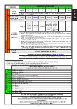
•
Value 1
: the Flash is restored at the rebalancing of the input that has generated the alarm
•
Value 2
: the Flash automatically deactivates after approximately 40 minutes or when the STC input
is rebalanced
•
Value 3
: the Flash is deactivated when the STC input is rebalanced
7
STC input
Red LED
FOLLOWS
STC
Change of
the status
with a Beep
Change of
status with
a Beep and
Red LED
Beep and
RED LED
are deacti-
vated
-
-
-
-
•
Value 1
: the RED LED is activated at the unbalancing of the STC input and is deactivated at the
rebalancing of the STC input
•
Value 2
: a BEEP signals both the unbalancing and the rebalancing of the STC input
•
Value 3
: the unbalancing of the STC input activates a BEEP and the RED LED, the rebalancing of
the STC input activates a BEEP and deactivates the RED LED
•
Value 4
: RED LED and BEEP are not activated by the unbalancing of the STC input
8
Enabling
None
a
t
a + t
v
a + v
T + V
a + t + v
Tampers
In this step, the tampers to activate or otherwise the
T T output
are enabled:
•
a
: anti-foam
t
: temperature
v
: anti-vibration
9
LED input
GREEN
LED DOES
NOT FOL-
LOW THE
STATUS
Alternative
sound to
the unbal
-
ancing
Green
status and
Alternative
sound to
the unbal
-
ancing LED
At the un-
balancing,
the red LED
repeats the
last signal
-
ling
•
Value 1
: the unbalancing of the LED input activates the GREEN LED, the rebalancing of the LED
input deactivates the GREEN LED
•
Value 2
: the unbalancing of the LED input activates the alarm with the Alternative Sound and the
Flash. The rebalancing deactivates the Sound while the Flash behaves based on its configuration.
•
Value 3
: simultaneously executes the actions of Value 1 and 2
•
Value 4
: the unbalancing of the LED input activates the visualisation of the STC input status with
the RED LEDs
E
N
G


