V1.0
INSTALLATION & SERVICE MANUAL
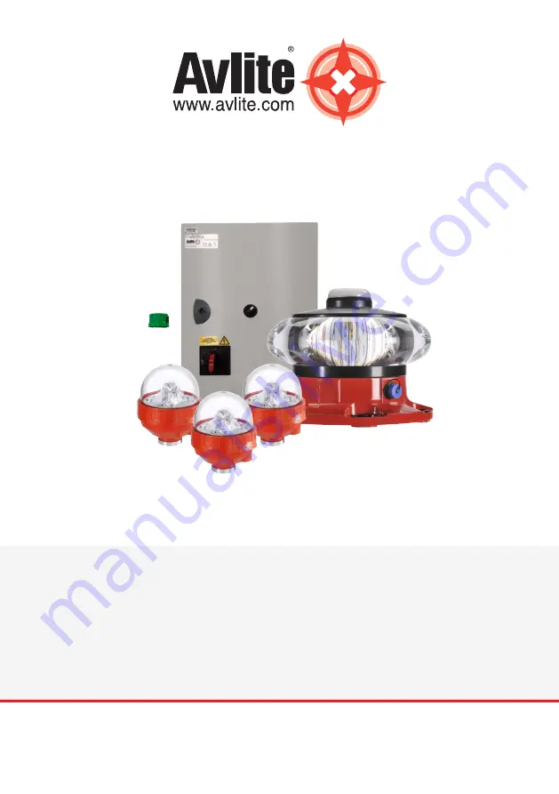
AV-OL-KT-A1
Obstruction Lighting Kit
FAA - A-1
Page 1: ...V1 0 INSTALLATION SERVICE MANUAL AV OL KT A1 Obstruction Lighting Kit FAA A 1...
Page 2: ...2 Version No Description Date Reviewed Approved Design 1 0 AV OL KT A1 Manual Launch September 2019 P Naidu W Evans M Sugars...
Page 3: ...ion and Setup 12 6 1 System Overview 12 6 1 1 GPS Synchronisation 12 6 1 2 L 864 13 6 1 3 L 810 F 15 6 1 4 T2 Controller 16 6 1 5 Interface Wiring 17 7 0 Unpacking Installation Wiring and Setup 18 7 1...
Page 4: ...vlite has been independently certified as complying with the requirements of ISO 9001 2015 quality management system By taking a few moments to browse through this booklet you will become familiar wit...
Page 5: ...ents in LED Light Emitting Diode technology as a light source The major advantage of LED s over traditional light sources is well established in that they typically have an operational life in excess...
Page 6: ...ilable in two input power configurations a universal AC 90 264VAC or 24 48 VDC solar compatible and comes with Star2M monitoring via GSM or SATCOM as options The best in class system power draw allows...
Page 7: ...75in 121mm 4 69in 119mm 5 4in 137mm PCD 7 874 200 00 6 Places 1 x L 864 Beacon AV OL FL864 9in 230mm 4in 104mm 6in 151mm Note Mounting hardware not included 1 x Control Unit 23 6in 600mm 15 8in 400mm...
Page 8: ...Radii X X X 0 002210 001 000 1 2 Model Rev Sealite 0 7 6 5 4 3 2 1 1 2 Zone Rev Model Rev ECR No Description Date General Tolerances Linear X X X X XX 1 2 0 3 0 1 Angular X X X 1 0 0 5 2 0 0 5 Radii...
Page 9: ...Fixtures Remote Monitoring and Control Avlite offers remote Star2M monitoring via GSM or SATCOM Operators can remotely monitor the status of their installation from a compatible device The system can...
Page 10: ...ounting accessories available Middle Junction Box Mounting accessories available Certifications and Compliance CE EN61000 6 3 2007 EN61000 6 1 2007 Quality Assurance ISO9001 2015 Protection Rating Jun...
Page 11: ...igned to guarantee the required beam pattern of the obstruction light Make sure any nearby obstacles do not impede the lights beam pattern When installing comply with all local electrical code s Mains...
Page 12: ...t mode all lights flash in synchronization with one another via integrated GPS synchronisation per the guidelines in the FAA 7460 1L Advisory Circular for lighting A1 structures In day mode all lights...
Page 13: ...base of the lens PCD 7 874 200 00 6 Places RED Status LED Lantern Status Lantern Condition Steady Flat Battery cut off is in effect OFF Battery voltage is less than 43 0V Slow High Voltage ON Battery...
Page 14: ...5 minutes Slow Flashing 1 5s on 1 5s off Operational Synchronized ON Normal operating condition Lantern is synchronized to GPS enabled lanterns 2 Quick flashes every 11s Operational Synchronized as Sl...
Page 15: ...oring via Star2M with either GSM or Satcom telemetry types as options By default the control unit comes with 2 dry contacts for external monitoring of both the L 864 and L 810 F light fixtures which r...
Page 16: ...ower Data cable 5 x 18 AWG Power Data cable 5 x 18 AWG L 810 F L 810 F L 810 F L 864 Power Data cable 5 x 18 AWG Top Junction Box Power cable 2 x 10 AWG Data cable 4 x 18 AWG T2 Controller Data cable...
Page 17: ...tervention A minimum of 4 satellites need to be in view for the built in GPS receiver to collect time data At dusk the light sensor will turn the light on If time data is available the light will come...
Page 18: ...PCU when the control panel power switch is toggled to the PWR position This may result in damage to the power sources WARNING DO NOT connect directly to the DC output of a generator or any other unre...
Page 19: ...obstruction lights Tools Needed not supplied Flush Cutter Tongue Groove Pliers Silicone Sealant Cable Jacket Trimmer optional Utility Knife Electrical Tape Insulated Terminal Crimper Wire Strippers 1...
Page 20: ...quence of steps can be adjusted for site requirements 1 Wire and test the system on ground level Conduct a basic functional check to ensure that the lights turn on as expected See section 7 3 Testing...
Page 21: ...d be plenty of clearance around all sides to allow direct access when the door of the control unit is completely open a Attach the required mounting hardware to the top and bottom of the Control Unit...
Page 22: ...tures The following considerations should be taken into account when mounting the external Photocell Mount in a reasonable location at eye level to ensure that it is easily accessible for servicing an...
Page 23: ...k positive conductor from the External Photocell to circuit breaker 5 labelled PC 24VDC on terminal block 1 in the Control Unit Connect the white negative conductor from the External Photocell to the...
Page 24: ...tower and bolting the L 864 to the bracket 6 Mount the top junction box Note Mounting hardware for junction boxes is not supplied 7 Wire L 864 to top junction box a Wire L 864 power cable to junction...
Page 25: ...larm Common COM conductor from the L 864 to the COM labelled terminal in the top junction box Connect the green alarm signal NC conductor from the L 864 to the NC labelled terminal in the top junction...
Page 26: ...conductor from the 48VDC terminal in the top level junction box to circuit breaker 2 label L 864 24VDC on terminal block 1 in the Control Unit Connect the white negative conductor from the 48VDC termi...
Page 27: ...AV OL KT A1 Obstruction Light Kit Installation Service Manual Latest products and information available at www avlite com 27...
Page 28: ...on labelled terminal on terminal block 1 in the Control Unit Connect the black alarm signal NC conductor from the top level junction box to the L 864 Alarm Signal labelled terminal on terminal block 1...
Page 29: ...AV OL KT A1 Obstruction Light Kit Installation Service Manual Latest products and information available at www avlite com 29...
Page 30: ...ount the L 810 F lights x3 Thread a pipe thread cord grip to the L 810 F and attach the light to an owner supplied bracket or optional Avlite Right Angle Mounting Bracket for low intensity fixtures wi...
Page 31: ...ction box Wiring instructions Power and Data cable Connect the red positive conductor from the L 810 F to the appropriately marked VDC terminal for marker 1 2 3 or 4 if installed in the mid level junc...
Page 32: ...appropriately marked Alarm COM terminal for marker 1 2 3 or 4 if installed in the mid level junction box Connect the Green NC conductor from the L 810 F to the appropriately marked Alarm NC terminal...
Page 33: ...d information available at www avlite com 33 Connect the White PC Input IN1 conductor from the L 810 F to the appropriately marked PC terminal for marker 1 2 3 or 4 if installed in the mid level junct...
Page 34: ...to the L 810F 24VDC labelled terminal on terminal block 1 in the Control Unit Connect the orange CTRL Alarm COM conductor from the middle junction box to the L 810F Alarm Common labelled terminal on t...
Page 35: ...AV OL KT A1 Obstruction Light Kit Installation Service Manual Latest products and information available at www avlite com 35 Refer to section 7 2 3 Cabling Requirements for recommended cable sizes...
Page 36: ...power conductors to the appropriate terminals i e AC Line 1 AC line 2 and AC Neutral on the power switch on terminal block 1 in the Control Unit The grounding conductor will be connected to the Ground...
Page 37: ...n synchronization b Day mode Uncover the External Photocell and check day operation is functioning as expected All lights should be off 4 Turn the Photocell Bypass Switch to Override and ensure that a...
Page 38: ...ee from debris i e snow leaves etc for reliable and continuous operation 9 0 Replacement Parts If replacement parts are required please call a local Avlite distributor and reference the Product or Con...
Page 39: ...Check the wiring of the malfunctioning lamp Junction box wiring Check junction box wiring All marker L 810 F lights out No Alarm Junction box wiring Check junction box wiring Cable to junction box Che...
Page 40: ...top light red flashing during the day Wired incorrectly or wire s lose Photocell failure PLC failure Check wiring between Photocell and PLC check wiring output of PLC Cover photocell Check if output v...
Page 41: ...AV OL KT A1 Obstruction Light Kit Installation Service Manual Latest products and information available at www avlite com 41 Notes...
Page 42: ...42...
Page 43: ...AV OL KT A1 Obstruction Light Kit Installation Service Manual Latest products and information available at www avlite com 43...
Page 44: ...ailable Avlite Systems Australia 61 0 3 5977 6128 Avlite Asia Pte Ltd Singapore 65 6908 2917 Avlite USA LLC USA 1 603 737 1311 We believe technology improves navigationTM avlite com info avlite com Ai...