AVK 02 Series Installation And Maintenance Instructions Manual Download Page 5

INSTALLATION AND MAINTENANCE INSTRUCTIONS - ORIGINAL VERSION

AVK GATE- AND SERVICE CONNECTION VALVES FOR GAS

SERIES 02, 03, 06, 36, 38 and 46

Parallel alignment of flanges is especially important in the case of the assembly of a valve into an existing system. 

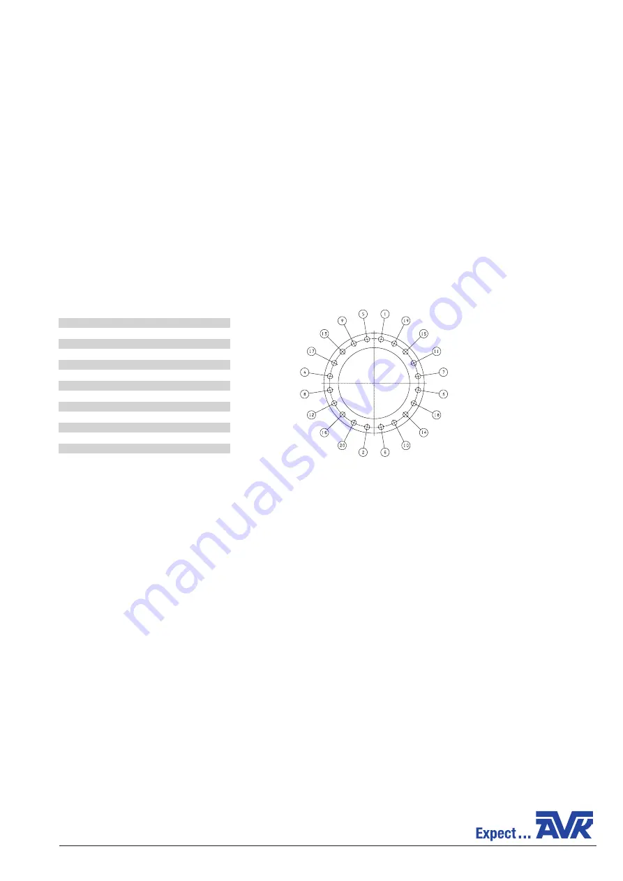
The bolting used for the flange connection must be checked for correct size, length, material and that all connection flange bolt 

holes are utilised. See table 1 for bolt sizes.

If a permanent extension spindle and road cover is used only a permanent telescopic extension spindle that is not completely 

collapsed (shall be extracted e.g. min. 50 mm) shall be used to avoid transfer any loads to the buried valve.

Gate valves with spigot pipe ends are to be installed either by means of appropriate welding or the use of a suitable coupling. 

For welding procedures please refer to pipe manufacturers’ specifications.  

For choice of coupling please consult an AVK representative.

Special care shall be taken when installing gate valves with purge points. The purge point pipes shall be protected from any 

sideway loads, both during handling and after installation.

13. OPERATION

Gate valves are typically operated with an extension spindle in below ground installations. In manholes or in above ground 

installations handwheels or electric actuators may be used. Ensure proper sizing of the handwheel and/or operating keys, 

extension spindles and actuators. Please refer to AVK datasheets for further information. When installing gate valves mounted 

with electric actuators, please observe closing torques and number of turns from the datasheet. When the valve is installed 

in a chamber with an extension spindle going to above ground level, ensure that no vertical force from the extension spindle 

presses down directly on the valve stem top. The extension spindle must be supported by wall mounts or similar to prevent 

vertical forces and thereby supporting the weight of the extension spindle.

When closing the gate valve ensure that the appropriate torque and number of turns are applied to the valve. See table 2.

14. PRESSURE TESTING

After installation, perform a pressure test before the trench is closed. Secure the pipe and gate valve against movement. If the 

pipeline and valve are tested with water prior to gas/air tests, ensure that the pipeline and valve are drained to prevent frost 

damage. AVK valves are designed to resist a test pressure of 1.5 x PN.

15. MAINTENANCE

The valve is designed to give long trouble free service without the need of routine maintenance. 

After the specified number of operation cycles have been reached the wear inside the valve shall be examined. If the wear is 

extensive, worn components shall be replaced or a new valve shall be installed. 

If internal or external leakage is suspected, it is recommended that AVK International be contacted to suggest suitable remedial 

action.

Page 5/8 


MI GateValvesGas Rev. N June 2019 GB


BOLT SIZES


DN           Working pressure (bar) 

  Quantity


mm 

PN 10    PN 16 

PN 10    PN 16


40 

M16 

M16 

4      


50 

M16 

M16      

4     


65 

M16 

M16        

4   


80 

M16 

M16   

8  

8       

  100 

M16 

M16      

8

  150 

M20 

M20 

8          

  200 

M20 

M20 

12          

  250 

M20 

M24       

12 

12    

  300 

M20 

M24       

12 

12  

  350 

M24 

M24       

16 

16 

  400 

M24 

M27       

16 

16

  450 

M24 

M27       

20 

20

  500 

M24 

M30       

20 

20

 600 

M27  M30 

20  20


Table 1

Figure 1

Summary of Contents for 02 Series

Page 1: ...e installation process or pipework that the valve is attached to Also consideration should be given to various loadings which can occur at the same time The valve on no account should be tampered with or modified in any way If for any reason work is to be carried out on the valve it is wholly the responsibility of the user to ensure the valve is depressurised and rendered safe prior to any fastene...

Page 2: ...nsible for any accidents arising from incorrect installation Likewise before during and after installation the applicable standards codes and regulations for installation and for the preven tion of accidents must be observed Note that especially for installations in hazardous environments ATEX regulations may apply 7 LIMITS OF USE Valves are permitted for use with Group 1 hazardous gases As standa...

Page 3: ...ssure and temperature do not exceed the above ratings If system testing will subject the valve to pressures more than the working pressure rating this should be within the production test pressure for the valve The maximum allowable pressure as specified is for non shock conditions Water hammer and impact for example should be avoided If the limits of use specified in these instructions are exceed...

Page 4: ... fully opened and closed to ensure it is operating satisfactorily Valves are precision manufactured items and as such should not be subjected to misuse such as careless handling or allowing dirt to enter the valve through the end ports Excessive forces during installation and operation must be avoided All special packaging materials must be removed When valves are provided with lifting lugs or eye...

Page 5: ...rs please observe closing torques and number of turns from the datasheet When the valve is installed in a chamber with an extension spindle going to above ground level ensure that no vertical force from the extension spindle presses down directly on the valve stem top The extension spindle must be supported by wall mounts or similar to prevent vertical forces and thereby supporting the weight of t...

Page 6: ...400 59 400 300 400 24 1600 59 50 450 300 450 450 25 1600 59 39 500 300 450 500 25 1600 59 43 600 500 600 25 3200 53 52 series 02 series 06 and 46 series 36 Table 2 1 Lower the pipeline pressure as much as the situation allows 2 Close the valve using the specified torque The replacment can also be done with the valve in open position but then it is required to completely isolate the valve from pres...

Page 7: ...eved approval CE 0085BO0317 from through requirements of the DVGW CERT GmbH following directive Josef Wirmer Strasse 1 3 D 53123 Bonn Phone no 49 228 91 88 807 Notified body no 0085 And conform to the essential Pressure Equipment Directive PED 2014 68 EU modules B Production Type requirements of the following and C2 directive And that they are in accordance Harmonised standards Supporting standard...

Page 8: ...203 from approval through certificate no DVGW CERT GmbH Josef Wirmer Strasse 1 3 D 53123 Bonn Phone no 49 228 91 88 807 Notified body no 0085 And conform to the essential Pressure Equipment Directive PED 2014 68 EU modules A Internal Production requirements of the following Control directive Series 03 DN25 and Series 36 DN25 are manufactured according to sound engineering practice SEP according to...

Reviews: