


E-
ON/
STA
NDB
Y
LAM
P/C
OVE
R
TEM
P
FRE
EZE
OF
F
FRE
EZE
/CA
PTU
RE
ROT
ATIO
N
INP
UT
TRA
NSF
ER
A Check of the Supplied Items and the Names of the Parts
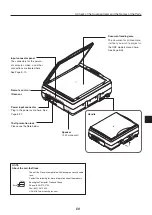
Names and Functions of the Parts (Projector)
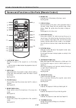
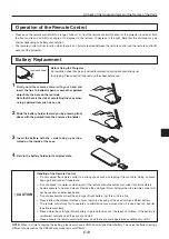
Remote control
IR sensor
Lens cap
Focus adjustment ring
Turn this to adjust the focus.
See Page E-22.
Projection lens
The image is projected from here.
* Be sure to remove the lens cap
before projecting.
Zoom lever
Turn this to adjust the screen size. See Page E-22.
Document cover
The document or printed material to be read is
placed under this cover.
See Page E-34.
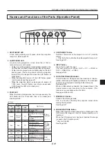
Operation panel
The buttons used for regular
operation are located here. See
Page E-11.
Air intake vent (Air filter)
Air is drawn into the projector from
here. There is an air filter to prevent
dust from entering the inside of the
projector. See Page E-50.
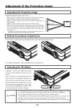
Tilt adjustment lever
Press here to adjust the tilt foot.
See Page E-22.
Tilt foot
This foot is used to adjust the vertical
angle of the projection as well as the left-
right balance. Turning it to the left ex-
tends it and turning it to the right shortens
it. See Page E-22.
Exhaust vents
Air is discharged from here.
Lamp unit cover
(Underneath projector)
The projection lamp unit is located inside.
See Page E-47.
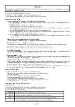
• During unit operation, do not obstruct the front of the lens. During operation, strong light through the
lens is projected. Obstruct the front of the lens causes fire or burn.
• During projection, be sure to remove the lens cap. Negligence to observe it may deform the lens
CAUTION
Summary of Contents for iP-40
Page 57: ...E 55 Power cable for Singapore...