Avigilon NVR4-VAL-12TB Manual Download Page 15

Replacing Hard Drives

The LED indicator flashes green, then orange and then off if it is about to fail. After it has failed, the status
indicator flashes orange four times a second. For more information about all the LED status indicators see

Hard Drive RAID Status Indicators

on page 10

.

To replace a failed hard drive:

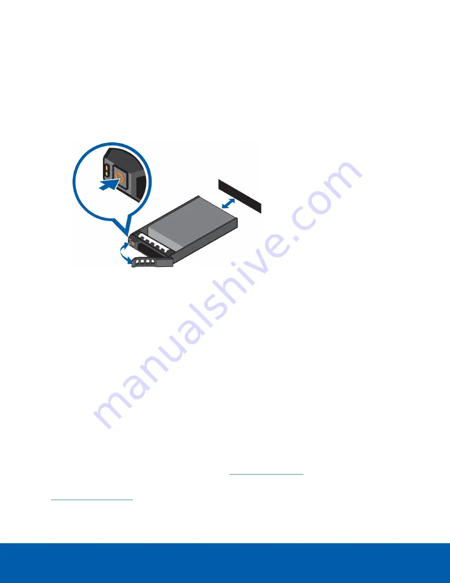
1. Locate the failed hard drive at the front or back of the recorder.

2. Press the release button on the front left of the hard drive.

3. When the handle is released, pull the hard drive out of the recorder.

4. Remove the four screws from the side of the hard drive carrier.

5. Lift the failed hard drive out of the carrier.

6. Insert a new hard drive into the carrier then screw it into place. The hard drive connectors should face

the back.

7. When the hard drive is secured in the carrier, insert the hard drive back into the recorder.

8. Once the hard drive is inserted all the way in, push the handle against the hard drive to lock it into

place.

The hard drive status indicator slowly flashes green, indicating the recorder has started rebuilding the hard
drive. Rebuilding the RAID hard disk array may take several hours. You can verify that the rebuilding has
started and monitor progress using the Server Administrator tool. Contact Technical Support if the rebuilding
process does not start.

Limited Warranty and Technical Support

Avigilon warranty terms for this product are provided at

avigilon.com/warranty

.

Warranty service and technical support can be obtained by contacting Avigilon Technical Support:

avigilon.com/contact-us/

.

Replacing Hard Drives

12

Summary of Contents for NVR4-VAL-12TB

Page 1: ...Installation Guide Avigilon Network Video Recorder NVR4 VAL 6TB NVR4 VAL 12TB NVR4 VAL 16TB NVR4 VAL 24TB...

Page 2: ...ark patent or other intellectual property rights of Avigilon Corporation or its licensors This document has been compiled and published using product descriptions and specifications available at the t...

Page 3: ...talling the Bezel 4 Configuring Windows 10 and Activating ACC 5 For More Information 6 Troubleshooting 6 Network Configuration 6 Checking System Health 6 Operating System Recovery By Avigilon Recovery...

Page 4: ...hardware A UPS system is used to protect critical equipment from mains supply problems including spikes voltage dips fluctuations and complete power failures using a dedicated battery It can also be...

Page 5: ...vices 4 Micro USB port Provides access to the Out of band OOB Management Network interface 5 Hard drives Provides access to hot swappable hard drives There are LED indicators on each hard drive The NV...

Page 6: ...networks 3 Power supply Primary power supply An optional secondary power supply is available NVR4 VAL 2NDPS NPC 4 Video connector Accepts a VGA monitor connection 5 Out of band management network int...

Page 7: ...onnecting Cables Refer to the diagrams in the Overview section for the location of the different connectors Make the following connections as required 1 Connect a KVM switch or separate keyboard mouse...

Page 8: ...local Active Directory domain Note This prompt appears only if an Active Directory is present on the network See the Windows Help and Support files for more information 3 Enter a user name for access...

Page 9: ...or more information Operating System Recovery By Avigilon Recovery Partition If you need to recover the Windows operating system the Network Video Recorder includes an onboard Avigilon recovery partit...

Page 10: ...complete the Windows setup process For more information see Configuring Windows 10 and Activating ACC on page 5 6 Navigate to C Avigilon Control Center Installation Files and run the ACC installer for...

Page 11: ...nto a USB recovery device 2 Plug the USB recovery device into the workstation 3 Repeatedly press the F12 key while booting the workstation 4 On the UEFI Boot menu select the USB recovery device Operat...

Page 12: ...ion Off Power is not connected Green Power is supplied to the recorder Flashing green Firmware update is being applied to the power supply unit Flashing green then turns off The redundant power supply...

Page 13: ...drive has its own set of LED indicators to show its activity and status Figure 3 1 Status LED 2 Activity LED The Activity LED flashes green when the hard drives are working The following table descri...

Page 14: ...LED Indicator Description Blinks green for three seconds orange for three seconds and off for six seconds The hard drive rebuild has been aborted Hard Drive RAIDStatus Indicators 11...

Page 15: ...screw it into place The hard drive connectors should face the back 7 When the hard drive is secured in the carrier insert the hard drive back into the recorder 8 Once the hard drive is inserted all th...

Reviews: