AXP340 Transponder Installation Manual
10 March 2014
01201-00
Issue AF
Page 2
AVIDYNE CORPORATION
2. Introduction
2.1 AXP340 Description
The AXP340 Mode S panel mount transponder is an ED-73E and DO-181E Class 1 compliant Mode S
level 2es datalink transponder, with support for extended squitter, elementary surveillance and SI codes.
The AXP340 is also a DO-260B Class B1S compliant ADS-B out participant. The AXP340 meets the
relevant environmental requirements of DO-160G/ED-14G, and is certified to ETSO C112d, ETSO C166b,
TSO C112d and TSO C166b.
The AXP340 transmitter power output is nominally 240 watts, and the transponder runs from either 14 volt
nominal or 28 volt nominal DC power supply with no configuration changes required.
The AXP340 transponder responds to both legacy Mode A/C interrogations and to Mode S interrogations
from both ground radar and airborne collision avoidance systems. In all cases, the interrogations are
received by the transponder on 1030MHz, and replies are transmitted on 1090MHz.
In the Mode S environment, S stands for Select, and a Mode S interrogator can selectively address a single
transponder. This allows accurate position plotting with lower reply rates, which in turn reduces frequency
congestion and interference. As a side benefit, power consumption by the transponder may be reduced, and
simple datalink services can be supported, such as ADS-B. It is however crucial to the reliable operation of
the system that each aircraft has a distinct Mode S address. The Mode S address is allocated by the
registration authority for the aircraft, and must be set when the AXP340 is installed.
2.2 Interfaces
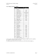
At the rear, the transponder has two Molex style connectors and a single antenna connector for blind mating
with the corresponding connectors in the mounting tray.
The interfaces provide the following services:
Parallel altitude input
Connection to an external altitude encoder using parallel Gray code.
Serial altitude input
Connection to an external RS232 altitude encoder or air data computer. Using
serial altitude data allows the transponder to report altitude with 25 foot
resolution.
Serial altitude output
Connection to a GPS or other device needing serial altitude data – this allows the
transponder to act as a repeater instead of requiring a second altitude encoder.
Ident input
External IDENT switch input.
Standby input
External standby input for dual transponder installations.
“On ground” input
Allows automatic flight/ground mode switching for aircraft with a squat switch.
Lighting bus input
Used to adjust the backlight and switch lighting intensity.
DME Suppression
Input
Input to limit interference between DME interrogations and transponder replies –
suppresses transponder whilst active.
Suppression bus I/O
ARINC compatible suppression bus signal used in aircraft with more sophisticated
suppression needs, both an input to and output from the transponder.
Audio output
Optionally used by the altitude monitor function.
Audio mute input
Toggle function to mute the audio output.


