


AXP340 Transponder Installation Manual
10 March 2014
01201-00
Issue AF
Page 8
AVIDYNE CORPORATION
5. Installation
5.1 Unpacking and Inspecting Equipment
Carefully unpack the transponder and make a visual inspection of the unit for evidence of any damage
incurred during shipment. If the unit is damaged, notify the shipping company to file a claim for the
damage. To justify your claim, save the original shipping container and all packaging materials.
5.2 Mounting
The AXP340 Mode S transponder must be mounted rigidly in the aircraft panel. The following installation
procedure should be followed, remembering to allow adequate space for installation of cables and
connectors.
Select a position in the panel that is not too close to any high external heat source. (The AXP340
is not a significant heat source itself and does not need to be kept away from other devices for this
reason).
Avoid sharp bends and placing the cables too near to the aircraft control cables.
Secure the mounting tray (p/n 01180-00) to the instrument panel via the six (6) mounting holes in
the tray. It is important that the tray is supported at the rear two mounting holes as well as the front
four.
Check that the locking mechanism is correctly oriented by unscrewing the locking screw if
required.
Slide the AXP340 transponder into the secured mounting tray.
Lock the AXP340 transponder into the mounting tray using a 3/32” Allen key, taking care not to
over tighten the locking screw.
5.3 Cooling Requirements
The AXP340 Mode S transponder meets all applicable ETSO requirements without forced air-cooling.
Attention should however be given to the incorporation of cooling provisions to limit the maximum
operating temperature of each unit when the AXP340 is installed in a typical panel or rack. The reliability
of equipment operating in close proximity in a rack can be degraded if adequate cooling is not provided.
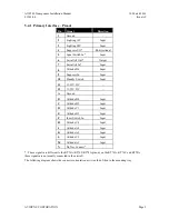
5.4 Electrical Connections
The AXP340 has two Molex edge connectors, one with 24 contacts, which is the primary interface, and a
second connector with 12 contacts which carries signals to support ADS-B. A single coaxial connector
attaches to the antenna. In simple installations it is possible to omit wiring for the second connector
altogether.
The Molex edge connector used in the AXP340 is similar to the connector used on the KT76A, KT76C and
KT78A transponders, and the common signals on the primary connector use the same contact positions and
are electrically compatible. The antenna connector is also compatible. Providing that the wiring is
appropriately installed, it is intended that you can upgrade a KT76A, KT76C or KT78A installation to the
AXP340 without any connector rewiring. Before doing that however, you MUST check that the wiring for
the existing transponder is in good condition.


