background image


¦

 chapter 2 bios setup and security feature              


2-7 

Exit Setup 


Item 

Selections / 
Sub-menu 

Description 

Saves 
Changes and 
Exit 

N/A 

After you have completed the BIOS 
settings, select this item to save all 
settings, exit BIOS Setup utility, and 
reboot. New system settings will take 
effect on next power-up. F10 key can be 
used for this operation.


Discard 
Changes 

N/A 

Discards changes done so far to any of 
the setup questions. 

Load Optimal 
Defaults 

N/A 

Load Optimal Default value for all the 
setup questions. F9 key can be used for 
this operation. 


Summary of Contents for AV4265-EH1

Page 1: ...i 1 AVERATEC User s Manual ...

Page 2: ...registered trademarks of Microsoft Corporation DOS Windows 95 98 ME 2000 NT XP are trademarks of Microsoft Corporation Product names mentioned herein may be trademarks and or registered trademarks of their respective owners companies The software described in this manual is delivered under a license agreement The software may be used or copied only in accordance with the terms of the agreement Thi...

Page 3: ...ing the Life of the TFT Display Panel Opening and Closing the Display Panel Audio Subsyste Adjusting the Volume in Windows Voice Recording Modem and Modem Setting Ethernet Adapte 2 BIOS SETUP AND SECURITY Entering the BIOS Setup Screen Leaving the BIOS Setup Screen BIOS Action Key Modifying the BIOS Settings Main Setu Advance Setup Boot Setup Security Setup Power Setup Exit Setup 3 BATTERY POWER P...

Page 4: ...System Memory 5 TROUBLE SHOOTING First Step Audio Problem Hard Disk Problem Optical Drive Problem Display Problem Keyboard and Mouse Problem CMOS Battery Problem Memory Problem Modem Problem Network Adapter Ethernet Problem PC Card PCMCIA Problem Performance Problem FireWire IEEE1394 and USB 2 0 Problem APPENDIX A Product Specification APPENDIX B Agency Regulatory Notices ...

Page 5: ...ws O S and symbols are used For instance Start Settings Control Panel Display means clicking the Start icon first then the Settings then the Control Panel then the Display icon n When you need to make a selection with the touch pad or mouse you will be asked to select or click or double click right click the item Note Text in this format and symbol means specific instructions commentary sidelights...

Page 6: ...uck away the power cord and any cables away from pedestrian traffic n When unplugging the power cord do not pull on the cord itself but pull on the plug n Keep the adapter away from children n The total ampere ratings of the equipment plugged in should not exceed the ampere rating of the cord if you are using an extension cord n The total current rating of all equipment plugged into a single wall ...

Page 7: ...age of the built in security feature provided by the BIOS Chapter 3 Battery Power Power Management In this chapter you will learn the fundamentals of power management and how to use them to achieve longer battery life Chapter 4 Upgrading Your Computer In this chapter you will learn how to upgrade the system memory Chapter 5 Trouble Shooting In this chapter you will learn how to solve common hardwa...

Page 8: ... chapter 1 getting to know the basics 1 1 C H A P T E R O N E GETTING TO KNOW THE BASICS This chapter introduces the features and components of the computer ...

Page 9: ...to PC games AveraBrite LCD Display The computer is equipped with a wide 13 3 inch TFT high resolution display panel for clear text and brilliant colors Expandability The system offers 2 upgradeable DDR SDRAM sockets for expansion allowing the user to easily increase the system s capacity as the need arises Built in Multiple Card Reader There is a built in 4 in 1 card reader to access many of the p...

Page 10: ...ators reveal the status of these functions Numeric keypad cap lock scroll lock WLAN ODD and HDD See the LED Status Indicator Section for details The LED Status indicators also reveal the status of the system power state and battery charging state See the LED Status Indicator Section for details 5 Power Suspend Button The power suspend button turns the notebook on and off and it also acts as a syst...

Page 11: ...the key launches a multimedia application that allows you to watch DVD movies or listen to music from the optical drive Front and Rear Views Warning Do not place any heavy objects on the top of notebook This may damage the display 1 Built in Stereo Speakers The built in speakers output the sound in stereo 2 Microphone Jack The microphone jack 3 5 mm diameter is where you connect a microphone 3 Ste...

Page 12: ...ur computer at a rate of up to 480 Mbps This port conforms to the latest USB2 0 plug and play standards 2 4 in 1 Card Reader The 4 in 1 Card Reader supports SD Card MMC Card MS and MS Pro Card 3 Optical Drive and Disk Eject Button and Manual Eject Key Hole If your computer comes with the Combo drive DVD RW DVD RW or DVD Dual drive you may save data onto a CD R CD RW DVD R and DVD RW disc Press the...

Page 13: ...tected When a DVD movie is played the output is scrambled to prevent analog recording 8 FireWire IEEE1394 1394a Port This is a high speed serial data port You may connect any Fire wire ready device to this port 9 PC Card Slot Type II PCMCIA and Card Eject Button The slot is where a PC Card Type II PCMCIA is inserted Press the eject button to release the PC Card Bottom View 1 Battery Pack and Batte...

Page 14: ...achine on hard surface only The bottom case may get very hot AC Adapter 1 DC out Connector The DC out connector docks to the power jack DC in on the computer 2 Adapter The adapter converts alternating current into constant DC voltage for the computer 3 AC Plug The AC plug to the AC wall outlet Warning Make sure you are using a standard 2 prong AC wall socket with a ground pin If not you may feel a...

Page 15: ...the notebook is ON Blinking blue light indicates the notebook is in suspend mode Orange light indicates the battery is being charged Blinking orange light indicates the battery level is low Green light indicates the battery is fully charged Blue light indicates the WLAN module is active Green light indicates the hard drive and or optical drive is being accessed Green light indicates the numeric ke...

Page 16: ...tness Fn F8 Turns Speaker Volume down Fn F9 Turns Speaker Volume up Fn F10 Turns off the Speaker Volume Fn Num Lk Enables the embedded keypad to work in numeric mode The keys act like numeric keypads in a calculator Use this mode when you need to do a lot of numeric data entry An alternative would be to connect an external numeric keypad Fn Scr Lk Press the Scroll Lock key and then press or to mov...

Page 17: ...pplication Menu Key This key brings up the popup menu for the application similar to a click of the right mouse button Embedded Numeric Keypad Press Fn NumLk to enable the embedded numeric keypad The numbers are printed in the upper right corner of a key in a color different from the alphabets This key pad is complete with arithmetic operators Press Fn NumLk to revert to normal character keys ...

Page 18: ...on Left Button Right Button Equivalent Tapping Action Execution Click twice quickly Tap twice at the same speed as double clicking the mouse button Selection Click once Tap once Drag Click and hold to drag the cursor Tap twice quickly and on the second tap hold finger to the touch pad to drag the cursor Access Context Menu Click once Tips on Using the Touch Pad 1 The double click speed is timed If...

Page 19: ...rnal backlight uses less power Extending the Life of the TFT Display Device Observe the following guidelines to maximize the life of the backlight in the display 1 Set the brightness to the lowest comfortable setting Fn F6 2 When working at your desk connect your notebook to an external monitor and disable the internal display Fn F5 3 Do not disable the suspend time outs 4 If you are using AC powe...

Page 20: ... in Windows 1 Click the speaker symbol in the task tray in Windows 2 Drag the volume control bar up or down to adjust the volume 3 To temporarily silence the speaker without changing the volume setting click Mute Voice Recording You will need to plug in an external microphone to the microphone connector to record sound You will need to use audio processing software to enable the built in microphon...

Page 21: ...the other end of the line into the analog phone wall outlet Depending on where your computer is used you may need to change settings in the modem The correct setting will allow you to maintain a stable connection in a country where its telecommunication system may be different to others To change the modem setting do the following 1 Go to Start Settings Control Panel Printers and Other Hardware an...

Page 22: ... the UTP cable into the network connector until the connector snaps securely into the receptacle 2 Either connect the other end of the cable to an RJ 45 jack wall outlet or to an RJ 45 port on a UTP concentrator or hub in the network Cabling Restriction for Networks The following restrictions should be observed for 100BASE TX networks The maximum cable run length is 100 meters m 328 feet ft For 10...

Page 23: ...eature 2 1 C H A P T E R T W O BIOS SETUP AND SECURITY FEATURE In this chapter you will learn how to enter the BIOS Setup Menu and manipulate various hardware control settings You will also learn how to use the built in security features ...

Page 24: ...gs for the computer s standard operations However there are occasions when you may be required to modify the default settings in the BIOS For example you may need to configure the BIOS power management APM settings if you are using DOS or non Windows operating system The BIOS allows you to set up passwords to limit access to users This is an important feature because a great deal of vital informat...

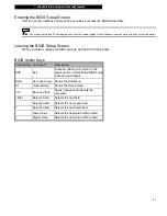
Page 25: ...OS settings exit the BIOS Setup Utility BIOS Action Keys Function Key Command Description ESC Exit Leaves a sub menu to return to the previous menu OR exits the BIOS setup while saving changes Enter Go to Sub Screen Shows the Sub Menu F1 General Help Shows the Help Screen F10 Save and Exit Saves changes and reboots the computer Tab Select a field Selects the next field Select an item Selects the n...

Page 26: ...d Disk Primary Master is where the HDD is connected Secondary IDE Master ATAPI CDROM The secondary master controls the ATAPI CD ROM drive Note The sub menu is not selectable Press enter to view information of the storage device Item Selections Sub menu Description LCD Auto DIMM Function Enable Disable Enable The system automatically reduces the LCD brightness when AC power is removed to save power...

Page 27: ...ed a USB Floppy Disk Drive before powering up it will appear as a Removable Device in the Boot Device selection menu Security Setup Boot Settings Configuration Item Selections Sub menu Description Change Supervisor Password N A Install or Change the Password Change User Password N A Install or Change the Password Boot Sector Virus Protection Disabled Enabled To enable or disable the boot sector pr...

Page 28: ...ed CPU performance is minimized to save battery life Automatic CPU adjusts its frequency automatically on AC power or battery power to save battery life Disabled SpeedStep function is disabled Power Button Mode On Off Suspend On Off When the power button is pressed the system is turned off Suspend When the power button is pressed the system enters the suspend mode Long Battery Life Mode Enable Dis...

Page 29: ...s select this item to save all settings exit BIOS Setup utility and reboot New system settings will take effect on next power up F10 key can be used for this operation Discard Changes N A Discards changes done so far to any of the setup questions Load Optimal Defaults N A Load Optimal Default value for all the setup questions F9 key can be used for this operation ...

Page 30: ... 3 battery power power management 3 1 C H A P T E R T H R E E BATTERY POWER POWER MANAGEMENT In this chapter you will learn the fundamentals of power management and how to use it to achieve longer battery life ...

Page 31: ...ou can have the system turn off its display after 2 minutes of inactivity to save power Efficient power management can help you work longer sessions before having to recharge the battery The Battery Pack Lithium Ion Battery Your notebook uses a six cell Lithium Ion battery pack that provides power when you don t have access to an AC outlet Note It is necessary that you charge the battery pack for ...

Page 32: ...rning Very Low battery condition occurs at 3 power remaining The red battery status LED indicator blinks and the system beeps at 4 second intervals When the notebook warns you of its low battery condition you will only have a few minutes to save your current work Warning Do not expose battery packs to temperatures below 0 degree Celsius 32 degree F or above 60 degree C 140F This may adversely affe...

Page 33: ...power management 3 4 Installing and Removing the Battery Pack To Remove the Battery Pack 1 Place the notebook bottom side up on a flat and secured surface 2 Push the latch and pull the battery s hard case away from the notebook ...

Page 34: ...he notebook plug the AC adapter into the notebook and an electrical outlet The charging time is approximately 4 6 hours when the notebook is turned off and approximately 6 10 hours when the notebook is turned on When the battery is fully charged the battery charge indicator becomes green Note If system runs at heavy loading or in a high temperature environment the battery may not be fully charged ...

Page 35: ...re the battery pack in room temperature Higher temperature tends to deplete the battery s power faster n Make good use of the power management function Save To Disk Hibernate saves the most energy by storing current system contents in a hard disk space reserved for this function n The life expectancy of the battery is approximately 300 recharges n See the notices section in the beginning of the us...

Page 36: ...nel window Schemes are easy to understand based on notebook usage scenarios and control not only processor power usage but other system peripherals as well Go to Start Settings Control Panel Performance and Maintenance and double click the Power Options icon Always on mode puts the processor into maximum performance mode which provides no power saving The other schemes control processor performanc...

Page 37: ... inactivity defined by the user No power or very little power is drawn from the battery module under this mode However depending on how much RAM that has been installed on your computer the amount of time the system requires to restore all its previous contents can range from 5 to 20 seconds For Windows 2000 XP users hibernation is handled by the operating system therefore no special disk partitio...

Page 38: ...ptions and click on the Advanced tab In the pull down menu select how you wish the power button to work as Note Actual dialogue box shown above may appear slightly different Warning In the When I close the lid of my portable computer pull down menu DO NOT select Do nothing otherwise the system will still run at high speed while the processor s fan grill is fully blocked by the closed LCD panel The...

Page 39: ...y condition Go to the Alarms tab in the Power Options Properties box If you wish to hear audible beeps click on the Alarm Action button and put a check on Sound Alarm Note Consult Windows user guide for more information on how to use Windows power management functions Note Actual dialogue box shown above may appear slightly different ...

Page 40: ...cking on the Battery icon at the lower right hand corner of the task bar If you do not see a battery or AC in icon go to Power Options Properties box and click on the Advanced tab Check off Always show icon on the task bar Select Max Battery if you want the system to enter suspend mode more often Or select Always On if your notebook PC is plugged into an AC power source Note Actual dialogue box sh...

Page 41: ...learn how to upgrade the DRAM Warning We strongly recommend that you send your notebook back to the manufacturer for upgrading When you upgrade your system please turn off the power disconnect the LAN and Modem cable first for your safety After the system upgrade please replace all the screws before turning on ...

Page 42: ...ty The SO DIMM can be 256MB or 512MB in capacity The SO DIMM is of type DDR1 has 200 pins and runs on 2 5V Warning Memory upgrade is a delicate process Please observe the following instructions carefully or have a qualified technician install it for you Damages due to mishandling of this procedure are NOT covered by the manufacture s warranty Warning Changing memory while your computer is in suspe...

Page 43: ...ily to discharge any static electricity Place the notebook on a flat surface and fully close the LCD lid 3 Locate and remove 7 Screw A s on the System Device Cover 4 Remove the System Device Cover The DIMM socket is now seen as shown below 5 If you need to remove an old DIMM from the socket press out on the latches located on both edges of the socket at the same time The DIMM should pop up to an a...

Page 44: ...e of approximately 30 degrees into the empty memory socket Then press it firmly so that the contact edge is driven into the receiving socket 7 Pivot the DIMM until the latches on both sides of the socket snap into place Note Notice the notch on the DIMM The notches should fit in the socket 8 Replace the System Device Cover back and tighten 7 Screw A s ...

Page 45: ...nd Step 4 from the previous section and remove Screw D 4 Find the keyboard latches near the upper edge and the side edges of the keyboard The latch is spring loaded It will retract when pressed and revert back to its original position when released Using a small blade to press the latch inward The keyboard tray should pop up slightly over the latch If the keyboard tray does not pop up try to gentl...

Page 46: ...s driven into the receiving socket 7 Pivot the DIMM until the latches on both sides of the socket snap into place Note Notice the notch on the DIMM The notches should fit nicely with the socket 8 Put the keyboard back to its position Make sure the upper edge of the keyboard now resides under the spring loaded latches Re attached Screw D Put the System Device Cover back on and tighten 7 Screw A s C...

Page 47: ... chapter 5 trouble shooting 5 1 C H A P T E R F I V E TROUBLE SHOOTING In this chapter you will learn how to solve common hardware and software problems ...

Page 48: ...ressing and holding any key n Check for any incorrect or loose cable connections Make sure the latches on the connectors latch securely on to the receptor end n Be sure you have not performed an incorrect setting on the hardware devices in the BIOS Setup utility A faulty setting may cause the system to misbehave If you are not sure of the changes you made try to restore all the settings to factory...

Page 49: ... the Sounds and Audio Devices Properties box make sure that Realtek AC97 Audio is the default playback device Sound cannot be recorded n You will need to plug in an external microphone to the microphone connector to record sound n Double click the speaker icon on the lower right corner of the taskbar to see if the microphone has been muted 1 Click Options and select Properties 2 Select Recording a...

Page 50: ...programs that you no longer use by moving them to an alternative storage medium floppy disk optical record able disk etc or uninstall programs that are no longer used n Many browsers store files in the hard drive as a cache to speed up the performance Check the program s Online Help for instructions on decreasing the cache size or on removing temporary Internet files n Empty the Recycle Bin to cre...

Page 51: ...eated in the tray Make sure the disk is firmly seated onto the spindle n The disk is damaged or not readable The disk cannot be ejected n Normally it takes a few seconds to eject the disk n If the disk cannot be ejected it may be mechanically jammed Straighten out a paper clip and insert it into the tiny hole next to the eject button This should eject the disk tray If not return the unit for repai...

Page 52: ...n touch pad performs erratically n Make sure there is no excess perspiration or humidity on your hand when using the touch pad Keep the surface of the touch pad clean and dry n Do not rest your palm or wrist on the surface of the touch pad while typing or using the touch pad The built in keyboard accepts no input n If you are connecting an external keyboard to the system the built in keyboard may ...

Page 53: ...ore details Memory Problems The Operating System does not show an increased memory capacity when you have already installed additional memory n Certain brands of memory module may not be compatible with your system You should ask your vendor for a list of compatible DIMM n The memory module may not be installed properly Go back to Chapter 4 to review the details of this operation n The memory modu...

Page 54: ... a different line or contact your local telephony company for service n Make sure the cable connection is firm n Try a different receiver number and see if the problem persists Network Adapter Ethernet Problems The Ethernet adapter does not work n Go to Start Settings Control Panel Performance and Maintenance System Hardware Device Manager Double click on Network Adapters and check if Realtek RTL8...

Page 55: ...ck Close in a few seconds Windows will prompt you to remove the card Performance Problems The computer becomes hot n In a 35 o C environment certain areas of the computer s back case are expected to reach 50 degrees n Make sure the air vents are not blocked n If the fan does not seem to be working at high temperatures 50 degrees Celsius and up contact the service center n Certain programs that are...

Page 56: ...vice Manager You should see an entry which reads Texas Instrument OHCI Compliant IEEE 1394 Host Controllers If it does not exist Windows has not detected the host controller or the device driver has not been installed properly If there is a yellow mark or red cross on the 1394 host controller it may be a device or resource conflict Replace or update the device driver from the factory CD ROM disk o...

Page 57: ... appendix A product specification A 1 A P P E N D I X A PRODUCT SPECIFICATION ...

Page 58: ...em Memory DDR SDRAM 333MHz PC2700 256 512MB 2 5 Volt 64 bit bus Two 200 pin DIMM sockets Max 2 GB Display 13 3 inch 1280x800 WXGA TFT display with 24 bit colors Intel Graphics Media Accelerator 900 Hardware Motion Compensation and IDCT Supported for MPEG1 2 Playback DirectX compatible Integrated with graphics accelerator Processor Core Logic Memory Type Default Memory Expansion LCD Panel Graphic A...

Page 59: ...less 2200 or MSI 6833A MiniPCI Interface IEEE802 11 B G LAN Ethernet Realtek 8100CL Ethernet function for 10 100Base TX network standards Windows 2000 XP Plug and Play compatible Automatic Jam and auto negotiation for flow control Auto Negotiation and Parallel detection for automatic speed selection IEEE 802 3u High performance 32 bit PCI bus master architecture with integrated DMA controller for ...

Page 60: ...Multimedia Card MMC Secure Digital Card SD Memory Stick MS Memory Stick Pro MS Pro Ports and Connectors One Microphone in jack One Headphone One FireWire IEEE1394 host connector Three USB 2 0 compliant connectors One standard network Ethernet connector RJ 45 One modem phone connector RJ11 One S video TV out output connector One DC in connector One 15 pin VGA connector One 4 in 1 Card Reader slot O...

Page 61: ... APM 1 2 Advanced Power Management ACPI 2 0 Advanced Configuration Power Interface Two Level Password Protections 32 bit access Ultra DMA PIO5 Mode support Multi boot capability Compatible with Microsoft Windows XP Physical Specification 12 44 W x 8 81 D x 1 25 1 35 H Inches 4 5 lbs with LCD Optical Drive and 6 cell battery pack Operating Temperature 5 to 30o C 41 to 86o F Operating Humidity 20 to...

Page 62: ... appendix B agency regulatory notices B 1 A P P E N D I X B AGENCY REGULATORY NOTICES ...

Page 63: ...o conditions 1 this device may not cause harmful interference and 2 this device must accept any interference received including interference that may cause undesired operation European Notice Products with the CE Marking comply with both the EMC Directive 89 336 EEC and the Low Voltage Directive 73 23 EEC and R TTE Directive 1999 5 EC issued by the Commission of the European Community Compliance w...

Page 64: ...sponsible for evaluation in a specific country Acceptable agencies are BSI UK OVE Australia CEBEC Belgium SEMKO Sweden FIMKO Finland DEMKO Denmark NEMKO Norway SETI Finland EANSW Australia SEV Switzerland IMQ Italy UTE France CCC China PSB Singapore PSE Japan BSMI Taiwan B Polish VDE Germany SASO Saudi Arabia n The flexible cord must be of a HAR harmonized type HO5VV F 3 conductor cord with a mini...

Page 65: ...to the laser beam n If the unit requires service contact an authorized service center n Ensure proper use by reading and following the instructions carefully n Do not attempt to make any adjustment of the unit CLASS 1 LASER PRODUCT APPAREIL A LASER DE CLASSE 1 LASERSCHUTZKLASSE 1 PRODUKT Warning Do not attempt to disassemble the cabinet containing the laser The laser beam used in this product is h...

Page 66: ... appendix B agency regulatory notices B 5 C AUTION Thispart ishot Be Care ful VORSICHT Diese Flache wird sehr heiss When you see this symbol be careful as this spot may be very hot ...

Page 67: ...EC S user s manual or service performed by other than AVERATEC 2 Defects resulting from software interfacing parts or supplies not supplied by AVERATEC which cause damage to the Portable Computer or cause abnormally frequent service calls or service problems 3 The Portable Computer has had its serial number or dating altered or removed NO IMPLIED WARRANTY INCLUDING ANY IMPLIED WARRANTY OF MERCHANT...

Page 68: ... other than AVERATEC 2 Defects resulting from software interfacing parts or supplies not supplied by AVERATEC which cause damage to the Battery or cause abnormally frequent service calls or service problems 3 If the Battery has had its serial number or dating altered or removed NO IMPLIED WARRANTY INCLUDING ANY IMPLIED WARRANTY OF MERCHANTABILITY OR FITNESS FOR A PARTICULAR PURPOSE APPLIES TO THE ...

Page 69: ...er than AVERATEC 2 Defects resulting from software interfacing parts or supplies not supplied by AVERATEC which cause damage to the Accessory or cause abnormally frequent service calls or service problems 3 If the Accessory has had its serial number or dating altered or removed NO IMPLIED WARRANTY INCLUDING ANY IMPLIED WARRANTY OF MERCHANTABILITY OR FITNESS FOR A PARTICULAR PURPOSE APPLIES TO THE ...

Reviews: