background image

Chapter 3

 13

Avaya M770 ATM Manager User Guide

Viewing Module Configuration Information

The Module Configuration dialog box provides information about the 
selected module. To view the configuration of an Avaya M770 ATM 
module:

1.  Select a module by clicking its label.

2.  Select 

Configuration >


Module.

Or 

Double-click the module label.

Or 

Right-click the module’s label and select 

Module Configuration

. The 

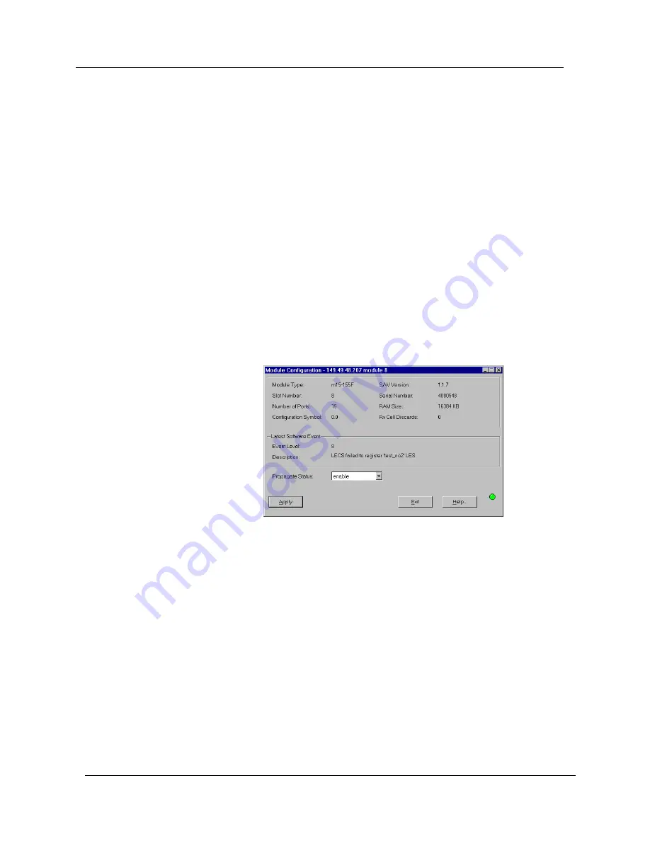
Module Configuration dialog box opens.

Figure 3-2.  Module Configuration Dialog Box

The Module Configuration dialog box provides module information such 
as the module type and software version, slot number, serial number, and 
other information about the module’s configuration.

For a full description of the fields in the Module Configuration dialog box, 
refer to Appendix B, Configuration Fields

Summary of Contents for M770

Page 1: ...Avaya M770 ATM Manager User Guide March 2001 ...

Page 2: ...ind express or implied and users must take full responsibility for their application of any products specified in this document Avaya disclaims responsibility for errors which may appear in this document and it reserves the right in its sole discretion and without notice to make substitutions and modifications in the products and practices described in this document Avaya Cajun P550 LANstack Cajun...

Page 3: ...apter 2 Agent Configuration 6 Overview of Master Agent and Sub Agents 6 Overview of Agent Configuration 7 Downloading New Agent Software 7 Viewing Agent Configuration Information 8 Designating Managers 8 Viewing the Managers Table 9 Adding Managers to the Managers Table 9 Removing Managers from the Managers Table 10 Editing the Managers Table 10 Chapter 3 ATM Device Configuration 11 Viewing ATM De...

Page 4: ... CPU Counters 31 Viewing Virtual Channel VC Counters 32 Viewing LECS Statistics 33 Viewing Management LEC Counters 34 Viewing DS3 Current Counters 35 Viewing DS3 Total Counters 36 Chapter 6 Managing Switch VCs 37 Viewing All VC Connections for a Device 37 Viewing All VCs on a Port 38 Chapter 7 Managing LANE Services 39 Resilient LANE 39 Choosing the LES Address for a LEC 39 Setting Up the LECS 40 ...

Page 5: ...49 Updating the Static Routes Table 50 Managing the PNNI Table 51 Viewing the PNNI Node Table 51 Editing the PNNI Summary Table 52 Appendix A Avaya M770 ATM Switch Manager Menus 54 Configuration Menu 54 Performance Menu 55 Administer Menu 56 Help Menu 56 Appendix B Configuration Fields 57 Appendix C Counter Fields 74 Appendix D Trap Fields 77 Index 78 ...

Page 6: ...ide The Purpose of this Guide The Avaya M770 ATM Manager guide contains the information needed to use the system efficiently and effectively Who Should Use This Guide This guide is intended for network managers familiar with network management and its fundamental concepts Organization of this Guide This guide contains the following subjects Preface Describes the guide s purpose and organization In...

Page 7: ... LECS statistics Managing Switch VCs Explains how to list all SVC connections for a switch Managing LANE Services Provides an overview of LANE services and their use with the Avaya M770 ATM Device Managing Routing Explains how to manage the static routes table and PNNI Avaya M770 ATM Switch Manager Menus Provides the structure of the menus in Avaya M770 ATM Manager Configuration Fields Provides a ...

Page 8: ...770 ATM Manager Chassis View including instructions for selecting elements and for using the menu bar and the toolbar buttons Starting Avaya M770 ATM Manager The following sections provide instructions for starting the Avaya M770 ATM Manager from the various supported management umbrellas Running Avaya M770 ATM Manager from Avaya MultiService Console To start Avaya M770 Manager from Avaya MultiSer...

Page 9: ...e click the row representing the Avaya M770 ATM Device Or Select Avaya Device Manager Running Avaya M770 ATM Manager from HP NNM for Windows NT and Solaris To start Avaya M770 ATM Manager from HP NNM Windows NT and UNIX 1 From the management platform map select an Avaya M770 ATM Device 2 Click in the OpenView toolbar Or Select Tools Avaya Device Manager Or 1 Right click on an Avaya M770 ATM Device...

Page 10: ...he overall device configuration and view hardware configuration Click Or Select Administer Launch Hub Manager The Avaya M770 Manager application opens For more information refer to the Avaya M770 Manager User Guide or on line help Selecting Elements Within the Chassis View you can select the following elements Modules Ports To select an element click it using the left mouse button The selected ele...

Page 11: ...Avaya M770 ATM Manager User Guide 4 Introduction Using Chassis View Features The Chassis View consists of a graphical representation of the device a Menu bar and a Toolbar Figure 1 1 Chassis View ...

Page 12: ... When you place the cursor on a toolbar icon for a second a label appears with the name of the button Table 1 1 Chassis View Toolbar Icon Description Menu Item Exit the application Configuration Exit Zoom View Avaya M770 ATM Device information Configuration Device Information View the Managers table Configuration Managers Table View Avaya M770 ATM agent information Configuration Agent View Avaya M...

Page 13: ...ks properly your network agent must be configured correctly Overview of Master Agent and Sub Agents The Avaya M770 ATM Device is a fully distributed switch Each module has its own switching and CPU power supply In order to present the device as a single and united entity one module is automatically elected as a Master Agent while the other modules are Sub Agents The NMA Network Management Agent LE...

Page 14: ... agent is not properly configured for your network or cannot communicate with Avaya MultiService Network Manager your network will not achieve its maximum functionality Therefore it is essential that your agent is configured correctly Downloading New Agent Software Download agent software using the Avaya MultiService Software Update Manager For instructions refer to the on line help for the Avaya ...

Page 15: ...sses and LEC information For a full description of the configuration fields in the Agent Information window refer to Appendix B Configuration Fields Designating Managers Agents send alarms to Manager workstations that are included in the agent s Manager list Alarms are not sent to any other network management stations NMS To properly manage an ATM device your station should be one of its designate...

Page 16: ...nagers Table lists the IP addresses and device names of the managers and their trap reporting status Adding Managers to the Managers Table To add managers to the list 1 Click on the IP address field and enter the IP address of the designated management station After the changes take effect the management station s name displays automatically in the Device Name column if available 2 Repeat the proc...

Page 17: ...st 1 Click on the IP address field and change the IP address of the designated management station After the changes take effect the management station s name displays automatically in the Device Name column if available 2 Click Apply The change takes effect immediately 3 Repeat the procedure for each manager Note It is recommended to keep the list limited to actual and relevant managers so as not ...

Page 18: ...n information Viewing Port Configuration Provides a detailed description of viewing port specific configuration information on Avaya M770 ATM modules Viewing the Virtual Port Table Provides a detailed description of viewing virtual port information Viewing Port PNNI Information Provides a detailed description of viewing PNNI information specific to a selected port Resetting Elements Provides a det...

Page 19: ...ice Information The Device Information dialog box opens Figure 3 1 Device Information Dialog Box The Device Information dialog box provides high level switch information such as the ATM device type system name contact location description and its ESI MAC address Note The Current ATM Prefix is only updated with the Configured ATM Prefix after the device is reset For a full description of the fields...

Page 20: ...le Or Double click the module label Or Right click the module s label and select Module Configuration The Module Configuration dialog box opens Figure 3 2 Module Configuration Dialog Box The Module Configuration dialog box provides module information such as the module type and software version slot number serial number and other information about the module s configuration For a full description ...

Page 21: ...guration dialog box opens Figure 3 3 Port Configuration Dialog Box The Port Configuration dialog box provides information such as the type of port and functionality the current state of the physical port and the virtual port and any faults that occurred on the port The fields in the Port Configuration dialog box may change according to the type of port selected Note To change the physical paramete...

Page 22: ...A confirmation box opens 3 Click Yes Or 1 Right click the port and select Enable Port A confirmation box opens 2 Click Yes Or 1 Open the Port Configuration dialog box 2 Change the Admin Status of the Physical Port to enable and click Apply The selected port is enabled To enable more than one port 1 Select multiple ports by holding down the CTRL key as you click the ports 2 Select Configuration Ena...

Page 23: ...ck the port and select Disable Port A confirmation box opens 2 Click Yes Or 1 Open the Port Configuration dialog box 2 Change the Admin Status of the Physical Port to disable and click Apply The selected port is disabled To disable more than one port 1 Select multiple ports by holding down the CTRL key as you click the ports 2 Select Configuration Disable Port A confirmation box opens 3 Click Yes ...

Page 24: ...rt Table The Virtual Port Table provides information such as the source port and module statuses signalling and termination types and neighbor information for each virtual port You can add edit and delete virtual ports in the Virtual Port Table Note The Admin Status must be set to disable to edit or add a virtual port For more information about changing the Admin Status refer to Editing a Virtual ...

Page 25: ... the fields in the Add dialog box For a full description of the fields in the Add dialog box refer to Appendix B Configuration Fields 3 Click OK The new virtual port is saved to the Virtual Port Table Note To add a new virtual port you must first assign a VPI range and the root virtual port VPI range must reduced For more information about setting the VPI range refer to Editing a Virtual Port on p...

Page 26: ...dit dialog box refer to Appendix B Configuration Fields 3 Click OK The changes are saved to the Virtual Port Table Deleting a Virtual Port To delete a virtual port from the Virtual Port table select a row in the Virtual Port table and click Delete The virtual port is deleted from the Virtual Port table Note Root Virtual Slot Port root cannot be deleted from the Virtual Port table You can only dele...

Page 27: ...and select PNNI The Port PNNI dialog box opens Figure 3 7 Port PNNI Window The Port PNNI dialog box provides information about the port s link type number of Hellos sent and received and information about the calculation of the cost of routing to and from the port The weight of various cost factors may be edited in the dialog box To apply any changes to the fields in the dialog box click Apply For...

Page 28: ...reset the entire Avaya M770 ATM Device with all its modules and subsystems 1 Select Configuration Reset Switch A confirmation box opens 2 Click Yes The entire device is reset Resetting the Module To reset a module 1 Select a module 2 Select Configuration Reset Module Or Right click a module and select Reset A confirmation box opens 3 Click Yes Only the selected module is reset ...

Page 29: ... device only ILMI information appears To view neighbor information 1 Select a port 2 Select Configuration Port Neighbor Info Or Right click the port and select Neighbor Info The Neighbor Info window opens Figure 3 8 Neighbor Information Window The Neighbor Info window provides information about the neighbor device connected to the port such as its name and addresses Note ILMI information appears o...

Page 30: ... Neighbor Info window To expand the Neighbor Info window 1 Click Neighbor PNNI Info The Neighbor PNNI Info window appears Figure 3 9 Neighbor PNNI Info Window To hide the neighbor PNNI information click Close PNNI Info For a full description of the configuration fields in the Neighbor Info window refer to Appendix B Configuration Fields ...

Page 31: ...also contains information for accessing and editing Severity Degrees in Unix and Windows NT This chapter includes the following sections Configuring Traps Defining the types of traps that are sent to the managers and the event log Viewing Traps Viewing the traps sent by the agent Assigning Severity Degrees Accessing and editing severity degrees ...

Page 32: ...u are configuring To configure traps 1 Select Configuration Traps The Traps Configuration dialog box opens Figure 4 1 Traps Configuration Dialog Box 2 Check the check boxes for the types of traps that you want the agent to forward to the management station that you are configuring 3 Click Apply For a full description of the traps in the Traps Configuration dialog box refer to Appendix D Trap Field...

Page 33: ...d NT OV Management applications using the Event Configuration application allow you to set fault severity degrees system wide for all devices on the network simultaneously or for specific devices per IP If the system wide setting and an individual device s setting disagree the individual device s setting takes precedence For more information refer to Severity Degrees in The Reference Guide Accessi...

Page 34: ...dit The Event Configurator window opens 4 Change the severity setting using the Severity pull down list 5 Click OK 6 Save the changes In HP OpenView and NT OV Select File Save In NetView Click Apply Editing Severity Degrees for Specific Devices To edit severity degree settings for specific devices 1 Select the enterprise which contains the fault whose settings you want to edit A list of the faults...

Page 35: ... Click OK 8 Save the changes In HP OpenView and NT OV Select File Save In NetView Click Apply Note All changes to the severity degrees takes effect only after the changes are saved Refer to the HPOV Event Configuration application help for more information ...

Page 36: ...terface of the CPU in each module Viewing Virtual Channel VC Counters Displays a breakdown of the cells for each Virtual Channel Viewing LECS Statistics Displays a breakdown of the LECS statistics in each module Viewing Management LEC Counters Displays a breakdown of the Management LEC information of the device Viewing DS3 Current Counters Displays a breakdown of the traffic flow activity for each...

Page 37: ...ple ports hold the CTRL key as you click additional ports To select all ports of a module click the module s symbol 2 Select Performance Port Counters The Port Counters window opens Figure 5 1 Port Counters Window Cell Counters are gathered for each selected port The display is automatically updated every thirty seconds To manually update the display click Start Click Clear Counters to reset all c...

Page 38: ...CPU Counters Or Right click the module label and select CPU Counters The CPU Counters window opens Figure 5 2 CPU Counters Window CPU Counters are gathered for each selected module The display is automatically updated every thirty seconds To manually update the display click Start Click Clear Counters to reset all counter values to 0 The exact time you click the Clear Counters button appears in th...

Page 39: ...t click a module and select VC Counters The VC Counters window opens Figure 5 3 VC Counters Window VC Counters are gathered for each selected module or port The display is automatically updated every thirty seconds To manually update the display click Start Click Clear Counters to reset all counter values to 0 The exact time you click the Clear Counters button appears in the Counters Cleared At fi...

Page 40: ...istics window opens Figure 5 4 LECS Statistics Window LECS Statistics are gathered for each selected module for which the local LECS is enabled The display is automatically updated every thirty seconds To manually update the display click Start Click Clear Counters to reset all counter values to 0 The exact time you click the Clear Counters button appears in the Counters Cleared At field When you ...

Page 41: ...ards and the number of SVCs Switched Virtual Connections that have failed to be set up To view Management LEC Counters select Performance Mng LEC Counters The Management LEC Counters window opens Figure 5 5 Management LEC Counters Window Management LEC Counters are gathered on the Master Agent The display is automatically updated every thirty seconds To manually update the display click Start Clic...

Page 42: ...ance DS3 Current Or Right click the module label and select DS3 Current The DS3 Current Counters window opens Figure 5 6 DS3 Current Counters Window DS3 Current Counters are gathered for each selected module The display is automatically updated every fifteen minutes After the device counters are updated the previous counters do not display To manually update the display click Start Click Clear Cou...

Page 43: ...click the module s symbol 2 Select Performance DS3 Total Counters Or Right click the module label and select DS3 Total Counters The DS3 Total Counters window opens Figure 5 7 DS3 Total Counters Window DS3 Total Counters are gathered for each selected module The display is automatically updated every fifteen minutes To manually update the display click Start Click Clear Counters to reset all counte...

Page 44: ...the M770 ATM Device Viewing all VCs on a Port A detailed description of displaying traffic through a VC to a selected port Viewing All VC Connections for a Device You can view a breakdown of the connections that are currently set up on the Avaya M770 ATM Device To list all VCs Click Or Select Configuration Switch VCs A table listing all the VCs opens Figure 6 1 Listing of all VCs The Switch VCs ta...

Page 45: ...tored 2 Select Configuration Port Total VCs Or Right click a port and select Total VCs The Total VCs window opens Figure 6 2 Total VCs Window The Total VCs window provides a list of the total number of VCs including SVCs and PVCs for the selected port The Total VCs window also provides a method for editing the SVC VCI range Note To edit the SVC VCI range the virtual port must be disabled Note The ...

Page 46: ...ulation in The Reference Guide Resilient LANE The Avaya M770 ATM Device in addition to LANE 1 0 supports proprietary redundant LANE services For more information on Resilient LANE refer to Proprietary Redundant Services in The Reference Guide Choosing the LES Address for a LEC When a LEC starts up it connects to the LECS as usual The LECS may have several different possible LESs for a particular E...

Page 47: ... LECS ELANs table and the LES BUS Table Configuring the Local LECS You can view and configure the local LECS using the LECS Configuration dialog box To configure the local LECS 1 Select the module you want to manage 2 Select Configuration LANE LECS Configuration The LECS Configuration dialog box opens Figure 7 1 LECS Configuration Window The LECS Configuration dialog box provides information on th...

Page 48: ...elect Configuration LANE Local Resilient LECS Table The Local Resilient LECS Table opens Figure 7 2 Local Resilient LECS Table The Resilient LECS Table provides information about the resilient LECSs such as their address format status and priority For a full description of the fields in the Resilient LECS Table refer to Appendix B Configuration Fields ...

Page 49: ...ust configure an ELAN name in this table for every ELAN that is to be used in your ATM network Viewing the LECS ELANs Table To view the LECS ELANs Table 1 Select the module you want to manage 2 Select Configuration LANE Local LECS ELANs Table The LECS ELANs Table opens Figure 7 3 LECS ELANs Table The LECS ELANs Table provides information about the ELANs that are recognized by the LECS such as the ...

Page 50: ...hanges to the fields 3 Click Apply The new ELAN is added to the LECS ELANs table 4 To clear the information in the fields of the dialog box click Add 5 To hide the lower part of the dialog box click Cancel Updating the LECS ELANs Table To update the LECS ELANs Table 1 Select an ELAN from the LECS ELANs table by clicking on it and Click Update Or Double click an ELAN from the LECS ELANs table The L...

Page 51: ... be viewed in the Registered LESs on ELAN window To view the Registered LESs on ELAN window 1 Highlight an ELAN in the LECS ELANs Table 2 Click the Registered button The Registered LESs on ELAN window opens Figure 7 5 Registered LESs on ELAN Window The Registered LESs on ELAN window lists the ATM address and LEC ID range of each registered LES for the selected ELAN Note Each module that hosts a re...

Page 52: ...s up to 16 combined LES BUSes To configure the LES BUS Table 1 Select the module you want to manage 2 Select Configuration LANE LES BUS Table The LES BUS Table opens Figure 7 6 LES BUS Window The LES BUS Table provides information on the LESs that are configured on the selected module such as the LESs name type status and registration mode Adding LESs To add LESs to the LES BUS Table 1 Click Add T...

Page 53: ...rt of the dialog box click Cancel Updating the LES BUS Table To update the LES BUS table 1 Select a LES from the LES BUS table by clicking on it and click Update Or Double click a LES from the LES BUS table The LES BUS table expands to allow editing The fields contain the LES information of the selected LES 2 Change the information in the lower part of the dialog box 3 Click Apply To hide the lowe...

Page 54: ...cking the Clients button in the LES BUS Table window Figure 7 8 LANE Clients on LES Window The LANE Clients on LES table provides information about those LECs that are on the selected LES such as their addresses states and LEC IDs For a full description of the fields in the LES BUS Table and LANE Clients on LES window refer to Appendix B Configuration Fields ...

Page 55: ...n the Avaya M770 ATM device database Managing PNNI Private Network Network Interface Information about the PNNI Interface of the Avaya M770 ATM Device Managing the Static Routes Table The Static Routes Table provides information about all routes in the Avaya M770 ATM Device database In the Static Routes Table you can View the ports associated with an ATM address View the origin of the routing entr...

Page 56: ...ck Or Select Configuration Static Routes The Static Routes table opens Figure 8 1 Static Routes Window The Static Routes table provides information on static routes such as port address prefix origin and status For a full description of the fields in the Static Routes table refer to Appendix B Configuration Fields ...

Page 57: ...e dialog box 3 Click OK The new route is added to the Static Routes table immediately To edit information in the Static Routes table 1 Select a row and click Edit The Edit dialog box opens with the current information for the selected route in the fields Figure 8 3 Static Routes Edit Dialog Box 2 Edit the information and click OK The information is updated immediately To delete information from th...

Page 58: ...To view the PNNI node table 1 Select Configuration PNNI Node Table The PNNI node table opens Figure 8 4 PNNI Node Table The PNNI node table provides node information such as Node Level Node ID Node ATM address and Node Peer Group ID You can update the Node Level and Node Peer Group ID You may want to change the peer group ID if multiple devices you have on the network have different peer group IDs...

Page 59: ... node advertises summaries of its Reachable Addresses For the lowest level node the ATM address of a device is the switch default summary as all directly connected hosts and edge devices that use ILMI for address registration get the switch prefix as the prefix to their address A separate PNNI Node Summary table exists for each of the five possible node indices The table for each node index contai...

Page 60: ...ed to the PNNI Summary table immediately To edit information in the PNNI Summary table 1 Select a row and click Edit The Edit dialog box opens with the current information for the selected route in the fields Figure 8 7 PNNI Summary Edit Dialog Box 2 Edit the information and click OK The information is updated immediately To delete information from the PNNI Summary table select a row and click Del...

Page 61: ...Cs Displays total VCs information for a port Port PNNI Displays PNNI information for a port Enable Port Enables the selected port s Disable Port Disables the selected port s Managers Table Displays managers configuration information Traps Displays trap configuration information Switch VCs Displays configuration information for switch VCs Virtual Port Table Displays the Virtual Port table Static Ro...

Page 62: ...nd packets going through the CPU in a selected module VC Counters Displays a breakdown of the cells going through a selected module LECS Statistics Displays the number of configuration requests successfully granted or rejected by the LECS on the module Mng LEC Counters Displays the amounts of traffic types flowing through the management LEC the total number of bytes that the management LEC receive...

Page 63: ...ster Menu Item Description ToolBar In Windows only Toggles the toolbar on and off Launch M770 Manager Launches the Avaya M770 Manager Table A 4 Help Menu Item Description Contents Opens the help module for information About Avaya M770 ATM Switch Manager Displays copyright information about the Avaya M770 ATM Manager ...

Page 64: ...ff The summary is advertised Address Type The type of RAs the summary applies to Possible types are Internal The summary applies to Reachable Addresses within the PNNI domain Exterior The summary applies to Reachable Addresses that are outside the PNNI domain Admin Status The administration status of the Physical Port Root Virtual Port or Virtual Channel Agent Slot Number The number of the slot ho...

Page 65: ...figured ATM prefix The configured ATM address prefix of the Avaya M770 ATM Device When the switch is reset this becomes the Current ATM Address Configured ELAN Name The name of the ELAN that the management LEC expects to join when it next leaves and re enters the network This information is sent to the LECS which uses it to determine the ELAN that the management LEC should join If you do not speci...

Page 66: ...vice Current ELAN Name The name of the ELAN that the management LEC has currently joined Current ILMI Status The current state of the ILMI protocol stack Current Signalling Type The type of signalling used by the root virtual port Current State Current state of the LEC with regard to the LES Possible states are other The LEC state is unknown noLesConnect The LEC is not connected to the LES lesConn...

Page 67: ... Threshold There are two packet discard thresholds for each option card called Early Packet Discard EPD and Partial Packet Discard PPD By default both thresholds have a default set limit and are enabled The Avaya M770 ATM Device uses EPD to discard entire AAL5 frames for ABR and UBR traffic rather than random cells from different frames when it determines that it is about to become congested The A...

Page 68: ...unique number which identifies a LEC on the ELAN LEC ID range The range of LEC IDs that the selected LES is responsible for LEC If Index The logical interface number assigned to the management LEC It is used to identify corresponding rows in the Interfaces MIB LEC Security The security mode of an ELAN Possible security modes are open Any LEC can request to join the ELAN This is the default securit...

Page 69: ...s that the management LEC is fully active LEC to LES assignment The algorithm according to which the LECS decides which LES s address to give a LEC This is only used if the registration type is set to distributed By Longest The LECS supplies the LES address that best matches the ATM address of the LEC By Equal Round Robin The LEC is assigned to the next distributed LES address in sequence each dis...

Page 70: ... name of the ELAN LES ELAN Type The type of ELAN Possible types are Ethernet Token Ring LES Name The name of the LES This must correspond to an ELAN with the same name LES Registration Type The LES registration mode to be supported by the LECS Possible modes are Prop LANE autosense The LECS will adopt the proprietary registration version from the first registering LES Prop LANE resilient The LECS ...

Page 71: ...255 ensures that it is always elected A priority of 0 ensures that it is never elected For more information refer to Resilient LECS in The Reference Guide Local LECS Status The operational status of the local LECS Possible statuses are Resilient Active Resilient Standby Not Resilient This field will be blank if the LECS location is remote Loopback The current type of loopback on a DS3 interface Th...

Page 72: ...e name can be assigned using the Avaya Name Server Neighbor ATM Address The address of the remote interface linked to the interface Neighbor Interface Name The name of the remote interface linked to the interface Neighbor IP The IP address of the immediate neighbor switch that the VC passed through or of the end station where the VC terminates Neighbor Sys Name The name of the remote device linked...

Page 73: ...e Administration Status cannot be down Therefore any change to the Node ID is only effective after the device is reset nrt VBR Admin Weight The administrative weight given to the nrt VBR non realtime Variable Bit Rate class of service when determining the cost of a link Number of Configured VCs The number of virtual channels that are currently configured Number of Ports The number of ports located...

Page 74: ... allows you to select the physical type of the port The type can be either SONET Synchronous Optic Network or SDH Synchronous Digital Hierarchy Port Classification The level of importance of the port Ports are classified as follows Backbone Device or switch connections most important Valuable Servers or critical users less important Regular Normal users least important For more information refer t...

Page 75: ...Green Okay By default status propagation is enabled for all ports and modules Proxy LEC Identifies if the selected LEC is a Proxy LEC or not Possible states are proxy non proxy PVC p2mp Leaf The number of point to multipoint leaf PVCs currently defined on this port PVC p2mp Root The number of point to multipoint root PVCs currently defined on this port PVC p2p The number of point to point PVCs cur...

Page 76: ...lly so that it will find the LES Remote at Address This module will advertise via ILMI the 20 byte LECS address specified here that is located on a remote module Remote at Resilient LECS This module will advertise via ILMI the resilient elected LECS address that is located on a remote module Remote at WKA This module will advertise via ILMI the LECS address at the WKA which is located on a remote ...

Page 77: ... left to right starting with number 1 as the leftmost slot This number may be 1 14 The agent module is inserted in either slot 15 or 16 A module which occupies two enclosure slots will be identified by the number of the second slot the right hand slot The slot number is the position in which the module is located There can be up to 5 modules in a device The Slot Number is set using the rotary swit...

Page 78: ...tates are on The summary is not advertised and all addresses that fall under this summary are not known in the PNNI domain off The summary is advertised SVC p2mp Leaf The number of point to multipoint leaf SVCs currently established on this port SVC p2mp Root The number of point to multipoint root SVCs currently established on this port SVC p2p Calling in The number of point to point SVCs that whe...

Page 79: ...ress Type on page 64 In the LECS ELANs Table Type of ELAN Refer To ELAN Type on page 67 UBR Admin Weight The administrative weight given to the UBR Unspecified Bit Rate class of service when determining the cost of a link UNI version The version of the User to Network Interface UNI protocol used in the ATM port VCI Virtual Circuit Identifier A unique numerical tag as defined by a 16 bit field in t...

Page 80: ...Guide 80 Configuration Fields VPI Range The VPI Range assigned to a physical port The VPI range is 0 7 VPort The number of the virtual port Xmt Hellos The number of Hello packets transmitted by the selected PNNI link Field Description ...

Page 81: ...ed due to insufficient resources Cell In Number of incoming cells Configuration Requests Successfully Granted The number of configuration requests successfully granted by the management LEC on the module Control Frames The number of LANE control frames that the management LEC has received In and transmitted Out Discards The number of frames that the management LEC has discarded because of insuffic...

Page 82: ...dress it sends it to the management LEC If it does not know the ATM address the LES forwards the address request to any proxy LECs that are registered with it so that they can respond directly if they own the address LE ARP responses The number of responses to LAN Emulation Address Resolution Protocol LE_ARP requests that the management LEC has received In and the number of LE_ARP requests that it...

Page 83: ...dule Total Rejected The total number of rejected CONFIGURE requests Total Rx Frames The total number of frames that have been received on the Fast Ethernet ports Total Traffic The total number of Token Ring frames processed by the module Total Tx Frames OK The number of frames of valid frame length that have been transmitted from the Fast Ethernet ports Unicast Packets The total number of unicast ...

Page 84: ...f the device Connection Traps A group of traps which report a problem in the ATM connection software e g Signalling ILMI Fault Traps A group of traps which report a fault in the device LANE Traps A group of traps which report a status change in one of the LANE components Management Traps A group of traps which report an error in software management events e g telnet memory Module Insert Traps The ...

Page 85: ...nt software 7 E Editing information in PNNI summary table 53 Managers Table 10 PNNI summary table 52 route in static routes table 50 Elements reseting 21 Elements selecting from Chassis View 3 Enabling physical ports 15 F Fault Management 24 First thing to do when starting 1 H Help menu 56 How to add ELANs to the LECS ELANs table 43 add information to PNNI summary table 53 add LESs to the LES BUS ...

Page 86: ...ion 14 view port counters 30 view registered LESs 44 view resilient LECS table 41 view the static routes table 49 view the virtual port table 17 view traps 25 view traps in a dialog box 26 view traps in the Event Log 26 view VC connections 37 view VC counters 32 L LAN Emulation choosing a LES address 39 managing services 39 resilient 39 LEC choosing the LES address 39 configuring 40 counters 34 LE...

Page 87: ... 46 static routes table 50 Using Chassis View 3 Chassis View features 4 the toolbar buttons 5 V VC connections for a switch 37 counters 32 viewing all VCs on a port 38 Viewing agent information 8 all VCs on a port 38 ATM switch information 12 CPU counters 31 35 36 device information 12 LANE clients 47 LECS ELANs table 42 LECS statistics 33 management LEC counters 34 managers information 9 module c...

Reviews: