background image


Using Windows CCFP Administration - Page 25 

Compact DECT  - Installation Manual 

Page 25 

38DHB0002UKFH – Issue 5 (27th October 2003) 

Starting CCFP Admin - Modem Connection 

Starting CCFP Admin - Modem Connection 

Starting CCFP Administration 

1.  Check that your modem is on and connected. 
2.  Locate and click on the CCFP Administration icon. 

– 

Windows 95/NT: 

Located in 

Start

 | 

Programs

 | 

CCFP 

Administration

3.  A start-up display appears. The base of the display shows the current 

communications settings that will be used to connect with the DECT 
system. 

4.  The moving bar across the display allows approximately 10 seconds to 

change the communication settings 

(see Changing the Communications 

Configuration on page 24)

 before it attempts to make the connection with 

the DECT system.  

5.  A configuration display appears. It will state: 

500 System Configuration Detected  


Ensure that the correct system configuration has been selected 


(see 

Changing the Communications Configuration

 on page 24).


6.  After a caution message, the main 

CCFP Administration

 screen 

appears with the Status page displayed. 

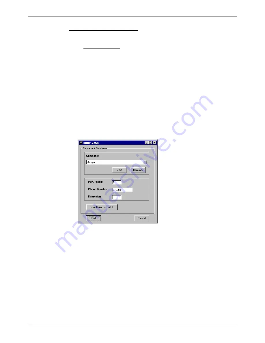
7.  In the Modem control section, select 

Dial Number

Dialer Setup


appears. 


–  Use this menu to select the DECT system you want to dial. Use the 

Add 

and 

Remove

 buttons to create and delete entries. If you do make 

any changes ensure that you select 

Save Database to File

 to save 

them. 

–  With the Company to which you want to connect displayed, click on 

Dial

. The Dialer Setup menu will close. 

8.  Watch the Receive Status display to check on the modem connection 

progress. 
– If 

CONNECT 

appears then the modem link has been established and 

you can start DECT programming by clicking on 

Proceed

– If 

CONNECT 

does not appear there is a problem with establishing a 

modem link that must be checked. Use 

File

 | 

Exit

 to close the program 

and then check the serial port, serial cable and DECT system. 

9.  After clicking on 

Proceed 

the screen shows handset 

Registration

 page. 

The progress indicator at the top-right of the screen shows the progress 
in copying down the DECT system's settings. 

Summary of Contents for Compact DECT

Page 1: ...Compact DECT Installation Manual 38DHB0002UKFH Issue 5 27th October 2003 ...

Page 2: ...m 21 Installing the Repeater Setup Program 21 Connecting a Repeater for Programming 21 Configuring a Repeater 22 Using Windows CCFP Administration 23 The CCFP Administration Program 23 Programming Connection 23 Installing CCFP Admin 23 Starting CCFP Admin Direct Connection 24 Changing the Communications Configuration 24 Starting CCFP Admin Modem Connection 25 MSF Status 26 Status Message 26 Upload...

Page 3: ... of six Plug top PSU PC Cable not supplied Twisted Pair Cable not supplied Up to 8 Handsets With max of 6 Simultaneous calls Plug orientation Viewed from bottom RJ11 RJ45 Access for Power PC twisted pair cable a b a b a b a b a b a b a b a b V24 INDeX Cable LAN IP Office Cable not supplied Required for DECT Integration A Compact DECT Base Station CDBS can support up to six simultaneous calls and u...

Page 4: ...peech quality obtained in its time slot to that in the same time slot on another carrier frequency If the current signal falls below acceptable limits and the other band is better the handset will change over to that band The Compact DECT systems use DCS DCA Dynamic Channel Selection Allocation to resolve availability of channels between handsets and base stations These processes allow a high dens...

Page 5: ...can handle up to two simultaneous calls These calls are borrowed from the CDBS Hence each call routed via the Repeater reduces the number of calls that the CDBS can handle The Repeater does not need any wiring connection to the CDBS The Repeater is designed for wall mounting and is supplied with a plug top PSU fitted with 2 mtrs of cable Size 100mm wide x 100 high x 40mm deep inc wall mounting bra...

Page 6: ...multaneous calls but these are borrowed from the CDBS Hence each call routed via Repeaters reduces the number of calls that the CDBS can handle During the site survey you will be attempting to determine three factors to achieve the customers requirements The best positioning of the CDBS The number of Repeaters required The best positioning of the repeaters To fulfill this you need to obtain the fo...

Page 7: ...ny factors that are unique to each site We can only guide you as to those things that are likely to affect base station coverage Obvious causes of signals problems Metal surfaces Concrete thickness greater than one metre Beware of Windows with reflective film or specialised glass e g Pilkington K These produce increased signal reflection and reduced signal pass through Wire Meshes and Grills with ...

Page 8: ...SSI Q52 signal it can accept audio input via a 3 5mm audio jack input for a manual audio quality check Power Supply Input 9VDC 150mA Subscribe Button Audio Input Power Socket The Survey Base Station is supplied with a suitable power supply terminated with an RJ11 connector The connector uses Pin 6 ve and Pin 5 ve to provide a 9V dc 150mA supply Audio In Socket Standard 3 5 mono jack socket input S...

Page 9: ...tered System ID appears below SYSTEM X where X 1 to 4 Press 9 to remove 6 You are returned to SUBSCRIPTION CREATE Press until SUBSCRIPTION REMOVE appears Repeat from step 4 for all previously entered System IDs 7 When completed press MENU twice and then press until LOGIN appears Press 9 to display SELECT LOGIN and press 9 again to display SYSTEM X where X 1 to 4 Use to select required system numbe...

Page 10: ...er Q52 52 Speech quality RSSI 64 Signal strength 3 Take the handset off hook as this will ensure more realistic figures If you have connected an audio source you will hear it whilst off hook Use this facility to check the audio quality only one handset can be off hook and receive the audio source at any time 4 Check the boundaries of the Survey Base Stations coverage where Q52 is greater than 52 a...

Page 11: ...t each item and check that all the necessary documentation and accessory items have been included Report any errors or omissions to the dealer who supplied the equipment 6 Ensure you read and understand any documentation included with any item Tools Required General 0 5mm flat blade screwdriver No 1 Phillips Crosspoint Cutter knife for cable ties Cable ties 3mm x 50mm Drill and masonry drill bits ...

Page 12: ...n temperature and humidity Check for the proximity of strong magnetic fields sources of radio frequency and other electrical interference Check there are no corrosive chemicals or gasses Check there is no excessive vibration or potential of excessive vibration especially on the cabinet mounting surface Power Supply Requirements Both the Compact DECT Base Station and Repeater s are designed to oper...

Page 13: ...leasing the four retaining tags clips one in each corner Cableentrybreak Wall mounting securingscrewholes PCBsecuringscrewhole PCBretaininglugs 2off PSUandPCconnectorsentrypoints Topcover securingclipsholes 4off CableClamp Useover appropriate retainingpillars 3 Remove the PCB by removing the securing screw and sliding the PCB up and out from the retaining lugs Put the PCB in a secure place 4 Use t...

Page 14: ...ipchannels Not Used 9 Feed the surplus twisted pair cable back out of the CDBS housing 10 Ensure that the bootstrap shorting strap is in the normal position and clip the front cover back on 11 Connect the other ends of the twisted pair cables to the Coms Platform analogue ports 12 Connect the CDBS to the PC either directly or via a modem See page 44 for cable details 13 Push the PSU modular plug i...

Page 15: ...This is found on a label covered by the handset battery It consists of a 5 digit handset type and then a 7 digit handset number separated by a space For other GAP compatible DECT handsets it is possible to discover the serial number see page 18 AC No An option account code of up to 7 digits If set then the account code is entered by the handset as part of the subscription process User Name Up to 1...

Page 16: ...e and that all previously subscribed System IDs are removed prior to subscribing for the first time see page 17 1 Press MENU and then until LOGIN appears then press 9 SELECT LOGIN appears 2 Press until SUBSCRIPTION CREATE appears then press 9 3 SEARCH ID appears Press until required system ID number appears The system ID is printed on the back of the Compact DECT Base Station The handset displays ...

Page 17: ...Press 9 CURRENT SYSTEM and the ID of that system appears 3 Press to select AUTO LOGIN and then press 9 to finish Removing a Subscription If necessary you can remove a subscription from the handset Do not do this lightly as you may not be able to re subscribe without assistance from your System Maintainer 1 Press MENU and then until LOGIN appears then press 9 2 SELECT LOGIN appears 3 Press until re...

Page 18: ... page 15 You should now be able to subscribe the handset System Testing Handover After completing installation including any Repeaters see page 19 and handset subscription perform the following checks Make test calls from all handsets With a call connected move through the areas that should be covered by the Base Station Check that no unexpected black spots exist With a call connected move through...

Page 19: ...6 Note When programming for Repeater Jumps you must start with Repeater 4 to CDBS followed by Repeater 5 to 4 and finally Repeater 6 to 5 E g Repeater 4 acts as a base station for Repeater 5 which in turn acts as a base station to Repeater 6 The range at which a Repeater can work will typically be between 50 and 150m within a building Each Repeater works in conjunction with an existing parent DECT...

Page 20: ...plied To mount a Repeater perform the following 1 Check the proposed position of the Repeater and ensure that A mains power supply is within 2 metres There is a minimum of 200mm clearance on all sides of the Repeater 2 Use the Repeater Wall Mounting Bracket see figure below as a template to mark the required holes Ensure that the Repeater is level Drill and insert the wall fixings for the No 6 rou...

Page 21: ... floppy disks as a self installing program It is also available from the web site https emea businesspartner avaya com index asp as a self extracting file Windows 3 x 1 Insert the first disk 2 In program Manager select File and then Run 3 Type a setup exe and then click on OK 4 Follow the on screen instructions for installing the Kirktool program Windows 95 NT 1 Insert the first floppy disk 2 Clic...

Page 22: ...t settings These may be empty CCFP This is the number of the CDBS Also ensure that Allow Subscription has been set to yes see page 16 Base to synchronize on The base station number default 1 of the CDBS with which the Repeater should synchronize or for repeater jumps see page 19 the number of the next repeater nearest to the CDBS Repeater number The number for the Repeater 4 Click on New and enter...

Page 23: ...CT Base Station to Modem Programming Cable on page 44 Both cable are plugged in to the PC Connection Socket see below Bootstrappins Bootstrapshorting strapinnormal position PCConnectionSocket For normal CCFP programming ensure that the bootstrap shorting strap is in the normal position For flash software uploads see page 26 the shortening strap must be across the two right hand vertical pins i e i...

Page 24: ...ration has been selected 6 After a caution message the main CCFP Administration screen appears If the connection is okay the screen shows handset Registration page The progress indicator at the top right of the screen shows the progress in copying down the DECT system s settings If the connection is not okay the screen shows the Status page with a sequence of TIMEOUT messages Use File Exit to clos...

Page 25: ...hanging the Communications Configuration on page 24 6 After a caution message the main CCFP Administration screen appears with the Status page displayed 7 In the Modem control section select Dial Number Dialer Setup appears Use this menu to select the DECT system you want to dial Use the Add and Remove buttons to create and delete entries If you do make any changes ensure that you select Save Data...

Page 26: ...tware for the Compact DECT may be supplied in the form of a flash ktb file or similar for upload to the system This upgrade file requires specific upload software Both of theses are available from the web site https emea businesspartner avaya com index asp as a self extracting files To upload software disconnect the power supply remove the top cover from the CDBS and set the bootstrap shorting str...

Page 27: ...msf file Loading Settings dat and msf text files WARNING As CCFP Administration is used to edit the live DECT system database opening a system settings file on the PC will immediately upload those settings to the connected system Therefore use this option with caution and ensure that the file being opened is correct for that system 1 To open current system settings select either the Registration o...

Page 28: ...t two options are not relevant to IP Office integration and hence are not discussed in this manual Preferences Several functions exist in Preferences as follows Advanced Options PC CCFP Version Diagnostics Advanced Options The following options area are available Backup and transfer of the system database and configuration setup Flash software upload Blocking and allowing all calls Password protec...

Page 29: ... or CDBS restart The CDBS requires the input of the time and date when first fitting on company premises to ensure correct time scales are seen in the event of investigating any problems on site The activity log will be seen in three parts Calls A snap shot of the real amount of calls associated against the Base Station number Total A snap shot of the amount of calls that have been received agains...

Page 30: ...ns Menus Page 30 Compact DECT Installation Manual Debug 38DHB0002UKFH Issue 5 27th October 2003 Debug The Debug Screen offers View DECT Handset PCS tab The PCS of all the connected DECT Handsets View Base Station PCS tab ...

Page 31: ...ciated with the directory number of another terminal e g a fixed desk telephone The use of Mobile Twin Number requires entry of a Mobile numbers switch licence on the INDeX When used having a mobile twin number has the following effects Calls to the fixed terminal also cause the DECT handset to ring If either the fixed terminal or DECT handset are busy callers receive busy tone or follow the fixed...

Page 32: ...on 1 From the Main Menu select System and then Switch Licences 2 Select Mobile numbers and enter the licence key Ensure that the option field displays 1 indicating it is the licence for Mobile Numbers with DECT Integration B Set the two wire port to DECT operation 1 From the Main Menu select Terminal and enter the directory number for a two wire port connected to the DECT 2 Select Port Type and se...

Page 33: ...ing to be collected A menu is provided on the DECT handset that allows the user to look up entries in the internal and external directories Entries can be identified by their first letter and entries can be browsed using the and DECT handset buttons You can make a call from the internal or external directory by pressing DECT handset s off hook button Selected person will be called You can configur...

Page 34: ... 15 The Local No must be the extension number allocated to the analogue port of the IP Office see page 35 3 Install DECT Configuration software on the PC running IP Office Administration see page 35 4 DECT configuration must be licenced see page 35 to utilize IP Office integration 5 Configure within the IP Office Manager program each User analogue port allocated to a DECT handset see page 35 6 Opt...

Page 35: ...n and in the right hand field right click and select New 4 Enter a valid Licence string for the Compact DECT obtained from your supplier The DECT Configuration Licences are for 8 16 or 64 extensions IP Office User Configuration A fixed range of analogue extensions Users must be allocated to DECT handsets Each User assigned to a DECT handset must be configured and the Internal directory set up Perf...

Page 36: ...u see below When completed the number of DECT handsets available to be twinned is displayed Enter the password of the host IP Office Tick this box to gain access to the Connect and configure menu and hence enable twinning see below The password must be that of the IP Office connected to the DECT 4 Check that either the Host Name or IP Address is displayed If not enter the IP address of the IP Offi...

Page 37: ...u have the option to Remove Selected Entry Highlight the entry and click on Remove Selected Entry 11 Repeat the procedure for all the master desktop phones that you wish to slave with DECT handsets remember that the DECT handset numbers will appear in sequential order starting from the numbers entered previously in the Handset Extension menu Click on OK when finished 12 The Configuration menu will...

Page 38: ...default password for Administrator is Administrator however this must be changed as early as possible 3 Open the Configuration Tree File Open The default password for the IP Office configuration is password however this password must changed as early as possible 4 In the Configuration Tree open User to display all available users 5 For the analogue port extension number assigned to the slave DECT ...

Page 39: ...me given to the Desktop phone in Telephone Number 9 Set Feature to VoicemailCollect as shown below 10 11 Select the SourceNumbers tab right click in the box and select Delete this tab must not contain any entries 12 Click OK to finish 13 For the User assigned to the Desktop phone right click in the User icon and select Edit and select the SourceNumber tab 14 Where the Desktop phone has been alloca...

Page 40: ... signal strength from each base station A value of 64 or greater is acceptable 3 Put the handset off hook this gives more accurate and realistic survey figures 4 To clear the display press until you hear a short bleep Handset Software Version The handset can provide details of its internal software version It is unlikely that you will need these details except if requested by the handset supplier ...

Page 41: ... Administration This page allows you to setup a library of messages Use the Message panel to set up the message s and the Send message to panel to allocate handsets On completion click on Send Message When MSF is first accessed a prompt is given which provides the option to download all the DAB user data available to the DECT The set of messages are stored as a file on the PC and not on the DECT s...

Page 42: ...er must press Enter after the alert to see the message When this option is on the message is displayed immediately after the alert Use Callback Number short messages with page call on only When on the message includes a callback number and when the handset user presses the key that number is dialled Alert Type This option set the ringing tone used by handsets to indicate the message Note that the ...

Page 43: ...ton below the text box You can now add and remove members from the group Adding members to a group 1 Highlight the user name you want to add in the list at the top of the page 2 Click on the Add button below the list of current member in the group Removing members from a group 1 Highlight the user name to remove in the list of current group members 2 Click on the Remove button below the list of cu...

Page 44: ...1 DCD 6 DSR GND 8 5 GND 8Pinmodular RJ45 Compact DECT Base Station to Modem Programming Cable 25 WayD typeMale CDBS Modem DCD 1 8 DCD DSR 2 6 DSR RXD 3 3 RXD RTS 4 4 RTS TXD 5 2 TXD CTS 6 5 CTS DTR 7 20 DTR GND 8 7 GND 8Pinmodular RJ45 When using a modem connection both modem should use the settings below Baudrate 19 2K Data 8 bits Parity None Stop Bits 1 The remote modem connected to the cdbs mus...

Page 45: ...6 17 Humidity 12 I Installation CCFP Admin 21 23 26 Interference 7 L Load 27 Load CCFP 24 25 Local number 15 M Mains supply 12 Mesh 7 Message Send 42 Messages 41 Save 27 Modem 24 Modem connection 24 25 Move user 15 MSF 41 MSF Log Status 26 O Open 27 Operating Frequency 4 P Packaging 11 Page call 42 Parts Required 11 Power supply 12 Presentation text 15 R Receive Status 26 Reflection 7 Registration...

Page 46: ...rom patent or other protective rights of Avaya or others Intellectual property related to this product including trademarks and registered to Lucent Technologies has been transferred or licensed to Avaya This document contains propriety information of Avaya and is not to be disclosed or used except in accordance with applicable agreements Any comments or suggestions regarding this document should ...

Reviews:

Related manuals for Compact DECT