background image

ASSEMBLY INSTRUCTIONS

7

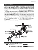
Place all parts from the box in a cleared area and position them on the floor in front of you. Remove 

all packing materials from your area and place them back into the box. Do not dispose of the packing 

materials until assembly is completed. Read each step carefully before beginning. If you are missing 

a part, please go to staminaproducts.com to the Services section and order the part needed, e-mail 

us at [email protected], or call us toll free at 1-800-375-7520 (in the U.S.). Our 

Customer Service Staff is available to assist you from 7:30 A.M. to 5:00 P.M. (Central Time) Monday 

through Thursday and 8:00 A.M. to 3:00 P.M. (Central Time) on Friday.

R

L

R

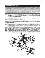
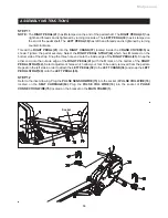
NOTE: 

Don’t  remove  or  damage  the 

DECAL(111)

  located  on  the  top  of  the 

MAIN  FRAME(1).

  The 

DECAL(111)

 is for preventing the 

SENSOR WIRE(29)

 and the 

PULSE CONNECTION WIRE(75) 

from dropping into the 

MAIN FRAME(1).

STEP 1:


 There is an 

“R”

 decal on one end of the 

FRONT STABILIZER(2)

. Attach the 

FRONT STABILIZER 

(2)

 to the 

MAIN FRAME(1)

 with the 

“R”

 decal end at right side and secure with 

CARRIAGE BOLTS                 

(M8x1.25x70mm)(81)

 and 

NYLOCK NUTS(M8x1.25)(104).

STEP 2:


Insert the 

STOPPER TUBE(48)

 through the 

MAIN FRAME(1)

 and secure with 

BUTTON HEAD 

BOLT(M8x1.25x15mm)(94).

NOTE:

  The 

PEDAL STRAPS(47)

 are pre-assembled and attached to the 

FOOT PEDALS(46).

 The pedal 

and strap assembly for the left side has an 

“L”

 decal. The pedal and strap assembly for the right 

side has an 

“R”

 decal.

STEP  3:


Insert  the 

PEDAL  SHAFT(44)

  through  the 

MAIN  FRAME(1).

  Place  the 

RIGHT  FOOT 

PEDAL ASSEMBLY(46R)

  onto  the  right  end  of  the 

PEDAL  SHAFT(44)

  and  place  the 

LEFT  FOOT 

PEDAL ASSEMBLY(46L)

 onto the left end. Secure the 

FOOT PEDALS

 with 

BUTTON HEAD BOLTS 

(M8x1.25x15mm)(94)

 and 

LARGE WASHERS(M8)(109)

 at both ends of the 

PEDAL SHAFT(44).

NOTE: 

You need to use two Allen Wrenches to tighten the 

BUTTON HEAD BOLTS(M8x1.25x15mm)(94)


at both ends of the 

PEDAL SHAFT(44)

 at the same time.

Meijer.com

Summary of Contents for A150-335

Page 1: ...Stamina Products Inc 2011 06 Exercise can present a health risk Consult a physician before beginning any exercise program with this equipment If you feel faint or dizzy immediately discontinue use of...

Page 2: ...ion with at least one adjustment hole visible in front of the seat before lifting rail to storage position This will prevent the seat from damaging the covers 13 Consult a physician prior to commencin...

Page 3: ...healthier lifestyle Should you have any questions please call our Customer Service Department toll free number 1 800 375 7520 Monday Thursday 7 30 A M 5 00 P M Central Time Friday 8 00 A M 3 00 P M C...

Page 4: ...the highest standards of manufacturing and quality control there can sometimes be missing parts or incorrectly sized parts If you have any questions or problems with the parts included with your AVARI...

Page 5: ...identify the warning caution and notice labels on the AVARI Conversion II Rower Recumbent Bike Please take a moment to familiarize yourself with all of the warning caution and notice labels EQUIPMENT...

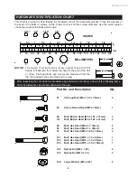
Page 6: ...bag and make sure that you have all the following items Some hardware may be already attached to the part MILLIMETERS 0 10 20 30 40 50 60 70 80 90 100 110 120 130 140 150 0 1 2 1 1 2 2 1 2 3 1 2 4 1 2...

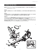
Page 7: ...5 from dropping into the MAIN FRAME 1 STEP 1 There is an R decal on one end of the FRONT STABILIZER 2 Attach the FRONT STABILIZER 2 to the MAIN FRAME 1 with the R decal end at right side and secure wi...

Page 8: ...T CAPS 79 onto HEX BOLT M10x1 5x125mm 103 and NYLOCK NUT M10x1 5 105 STEP 6 Connect the lower end of the SUPPORT TUBE 56 to the MAIN FRAME 1 with HEX BOLT M10x1 5x85mm 101 and NYLOCK NUT M10x1 5 105 P...

Page 9: ...BACK CUSHION 69 onto the SEAT CARRIAGE 64 with HEX BOLTS M6x1x30mm 96 STEP 10 Turn the knob of the SPRING PIN 67 counterclockwise and lock the knob in the release position refer to the inset drawing S...

Page 10: ...p Snap the three hole end onto the inside edge of the RIGHT PEDAL 41 Snap the other end onto the outside edge of the RIGHT PEDAL 41 with the R mark on the bottom of the RIGHT PEDAL STRAP 42 Select adj...

Page 11: ...ST 31 onto the MAIN FRAME 1 and secure with SCREW M5x18mm 84 STEP 14 Install two AA batteries into the METER 30 the batteries are not included See page 13 for detailed battery installation instruction...

Page 12: ...o the bike sits on the floor without rocking MOVING The AVARI Conversion II Rower Recumbent Bike has a pair of MOVING WHEELS 76 on the FRONT STABILIZER 2 Grasp the RAIL CAP 55 to move the AVARI Conver...

Page 13: ...total accumulated distance you have traveled from zero to 999 9 miles The total accumulated distance is retained when the meter is turned off Displays the calorie consumption from zero to 999 9 Kcal...

Page 14: ...the Recumbent Bike mode or the Rower mode When the SPRING PIN 67 locks the SEAT ASSEMBLY to the RAIL 52 the AVARI Conversion II Rower Recumbent Bike is in the Recumbent Bike mode When the SPRING PIN 6...

Page 15: ...tracks in the RAIL 52 with an absorbent cloth 3 Verify that all nuts and bolts are present and properly tightened Replace missing nuts and bolts Tighten loose nuts and bolts 4 Verify that the CAUTION...

Page 16: ...he REAR SUPPORT 62 in position with the PULL PIN 63 B D A C Grasp Here To Move 1 To store the AVARI Conversion II Rower Recumbent Bike simply keep it in a clean dry place 2 To avoid damage to the elec...

Page 17: ...r maximum heart rate zone Start at the lower intensity and build up to higher intensity as you become more aerobically fit If you feel dizzy or lightheaded you should slow down or stop exercising To d...

Page 18: ...down should include the stretches listed above and should be completed after each strength training session Lower Body Stretch Place feet shoulder width apart and lean forward Keep this position for 3...

Page 19: ...OF THE PRODUCT TO THE PURCHASER This limited warranty is not transferable IF ANY PART OF THE PRODUCT IS NOT IN COMPLIANCE WITH THIS LIMITED WARRANTY OR ANY IMPLIED WARRANTY THE REMEDY OF REPAIR OR REP...

Page 20: ...PRODUCT PARTS DRAWING FRONT BACK 20 Meijer com...

Page 21: ...24 Roller Spacer 2 25 Handlebar 1 26 Foam Grip 2 27 Tension Knob 1 28 Magnet 1 29 Sensor Wire 1 30 Meter 1 31 Meter Post 1 32 Top Cover 1 33 Left Cover 1 34 Right Cover 1 35 Crank Cover 2 36 Left Cra...

Page 22: ...d M5 x 0 8 x 15mm 12 88 Bolt Round Head M6 x 1 x 15mm 4 89 Bolt Round Head M6 x 1 x 30mm 4 90 Bolt Flat Head M8 x 1 25 x 16mm 2 91 Bolt Flat Head M8 x 1 25 x 25mm 1 92 Bolt Flat Button Head M8 x 1 25...

Page 23: ...SERVICE For your convenience Stamina s customer service representatives can be reached by email at customerservice staminaproducts com or by phone at 1 800 375 7520 in the U S Our customer service rep...

Reviews: