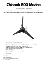
background image

Table of Content

1. SAFETY 

...............................................................................................1

1.1 Mechanical Hazard ............................................................................2
1.2 Electrical Hazard ................................................................................2

2. SYSTEM SPECIFICATION

 ...................................................................4

2.1 Specification .......................................................................................4
2.2 Performance ......................................................................................4
2.3 Wiring Requirement ............................................................................5

3. SYSTEM PROTECTION

 ......................................................................7

3.1 Digital-controlled MPPT ......................................................................7
3.2 Mechanical Stop Switch ....................................................................10

4. PACKAGE CONTENTS 

.....................................................................12

5. INSTALLATION PROCEDURE

 .........................................................13

6. MAINTENANCE 

.................................................................................19

7. FAQS 

.................................................................................................20

8. WARRANTY

 .......................................................................................25

APPENDIX A IMPORTANT SAFETY INSTRUCTIONS

 ........................28

APPENDIX B BEAUFORT WIND SCALE

 .............................................30

APPENDIX C MPPT CHARGE CONTROLLER

 ...................................31

APPENDIX D REGISTRATION FORM

 ..................................................37

Summary of Contents for 1200 Watts Wind Turbine

Page 1: ...1200 Watt Windmill User s Manual Ver 2017 11 24...

Page 2: ...Wiring Requirement 5 3 SYSTEM PROTECTION 7 3 1 Digital controlled MPPT 7 3 2 Mechanical Stop Switch 10 4 PACKAGE CONTENTS 12 5 INSTALLATION PROCEDURE 13 6 MAINTENANCE 19 7 FAQS 20 8 WARRANTY 25 APPEN...

Page 3: ...on your wind turbine with activation of mechanical stop switch 3 Listen to your wind turbine should you hear any mechanical noise maintenance may be required please contact The Products Customer Serv...

Page 4: ...at in a wiring system is often a result of too much current flowing through an undersized wire or through a bad connection Please consult wire guide table below Batteries can deliver a dangerous amoun...

Page 5: ...ain Also the Turbine possibly brakes in extreme weather conditions The rooftop may not be the best place for your Turbine Here are three reasons a The flow is more turbulent above the rooftop and lead...

Page 6: ...hows the performance you should expect from your wind turbine During smooth steady wind speed you can expect to see output resembling the curve illustrated below To convert between power and current u...

Page 7: ...stance from the MPPT to your turbine should not exceed 60 meter for safety reasons Be sure to include the height of tower Caution 2 Please review the above wire gauge table to install the correct wire...

Page 8: ...tem NOTE Please apply the Mechanical Stop Switch simultaneously Refer to the SEC 3 2 for detailed info System wiring diagrams ON OFF R S T Digital MPPT Battery Red Lead Blue Lead Black Lead Blue Lead...

Page 9: ...nge Smart load management function braking function 1 LCD Display 7 DC Output Negative 2 Data Port 8 Cooing Fan 3 LED Indicator green light voltage 9 R AC Input Red Wire 4 LED Indicator green light cu...

Page 10: ...rent Protection PR4 MPPT Overheat Protection PR5 Low Battery Warning PR6 Turbine Overheat Protection PR7 Wind Gust Protection When the auto protections above occur the braking will last 3 minutes befo...

Page 11: ...If the parameter of voltage and current is wrong then the braking system will be turned on Protection for Wind Turbine The MPPT charge controller can sense the rotation speed of wind turbine If the ro...

Page 12: ...ical 3 phase AC brake During periods of high winds upwards of 35 mph 16 m s it is strongly advised to utilize both MPPT brake and mechanical stop switch The use of mechanical stop switch will not affe...

Page 13: ...is provides a parallel connection Test the connection of your mechanical stop switch at the point of initial installation Push the brake ON You should see the Turbine stop its rotation Continue to app...

Page 14: ...e handle with care Part List Blade Base Generator Hub Nose Cone Tail Generator 1 Hex Screw M5XL50 1 Blade 3 Hex Screw M8XL40 6 MPPT Charger Controller 1 Hex Screw M5XL20 4 Hub 1 Set Screw M8XL12 4 Tai...

Page 15: ...13 5 INSTALLATION PROCEDURE Step 1 Open the boxes to ensure all parts are present Step 2 Fasten the blades on hub with 6 x hex screws M8XL40 6 x nuts M8 and 12 x washer M8 by using hex key 6mm...

Page 16: ...14 Caution Make sure that all of the bolts are secured and the dots all face to the operator...

Page 17: ...hrough the pole Install the Turbine to your chosen tower securely and fasten the bolts by using the hex key 4mm The outside diameter of the iron pipe should be 48 3 mm the thickness of iron pipe shoul...

Page 18: ...Step 4 Install the hub Put the ring on the shaft Insert the double head round key to the hole of the shaft Put the hub onto it and fasten the sleeve M16 by using wrench 16...

Page 19: ...Step 5 Tail Fin assembly Connect the tail fin to the Turbine with 4 x hex screw M5XL20 4 x set screw M8XL12 and 4 x spacers by using hex key 3mm 17...

Page 20: ...Step 6 Put the nose cone to the hub Apply pressure to the connections to ensure a secure fit Fasten the nose cone with hex screw M5XL50 by using hex key 3mm Step 7 Final product diagram 18...

Page 21: ...ades if damaged It is important to not use blades that are damaged as you will lose overall balance resulting in a decrease in efficiency Should you notice damage to the blades you must replace all 3...

Page 22: ...s it is necessary to lay down the Tower to offer further protection 3 How long will the bearings or other wearing parts last According to engineer calculations the bearings should have a 10 year life...

Page 23: ...ifference between copper and aluminum wire Generally aluminum wire is less conductive so it must be bigger for the same amp load and resistive losses as copper The wind turbine uses copper or tinned c...

Page 24: ...base may help prevent shocks to persons touching the tower due to lightning or electrical faults Please take the time to review the National Electrical Code NEC and local building and zoning regulati...

Page 25: ...ribution of EMF noise across both wires which serves to cancel out the electrical noise created This technique can be used on the wind turbine power lines on the radio s power lines and on transmissio...

Page 26: ...cult to turn When the wires are disconnected it should spin freely Should this not be true please contact supplier or manufacturer 4 With your wind turbine connected to your battery bank use an electr...

Page 27: ...he warranty does not apply to a equipment materials or supplies not manufactured by manufacturer b Product that has been modified or altered other than by manufacturer or without prior manufacturer s...

Page 28: ...RECTLY OR INDIRECTLY BY USE OF THE PRODUCT BY ANY PERSON ALL OTHER WARRANTIES ARE EXPRESSLY WAIVED BY THE CUSTOMER Warranty Claims Return Policies To be eligible for service under this warranty custom...

Page 29: ...t that is returned to them without a proper RA LIMITATION OF LIABILITY UNDER NO CIRCUMSTANCES WILL THE MANUFACTURER OR ITS AFFILIATES OR SUPPLIERS BE LIABLE OR RESPONSIBLE FOR ANY LOSS OF USE INTERRUP...

Page 30: ...et The better location of your wind turbine requires avoiding personnel or animal activities within a 33 ft 10 m radius and human habitation and wildlife within a 66 ft 20 m radius 2 The height of ins...

Page 31: ...on still affect sleep for some sensitive people and animals 4 Check the three wires from the wind turbine output periodically Please check AC current from your MPPT If the outputs are not consistent p...

Page 32: ...air 1 3 2 6 0 55 1 66 1 24 3 73 2 Light breeze 4 6 7 12 1 95 3 33 4 35 7 46 3 Gentle breeze 7 10 13 19 3 61 5 27 8 08 11 81 4 Moderate breeze 11 16 20 30 5 55 8 33 12 43 18 64 5 Fresh breeze 17 21 31...

Page 33: ...8 6v 57 2v FLOAT voltage set point 13 6v 27 2v 54 4v Non Sealed Lead Acid 24V 24V 48V ABSORB voltage set point 14 8v 29 6v 59 2v FLOAT voltage set point 13 6v 27 2v 54 4v Multi Stage Battery Charging...

Page 34: ...ch the absorb voltage set point then the absorb charge will last for 2 hours only A bulk charge will be re initiated if the battery voltage is not sustained at the absorb voltage set point Float This...

Page 35: ...y cycles by turning on power supply voltages in the proper sequences and making internal calibrations At wakeup the MPPT closes its relays and will then start sweeping the input voltage the initial sw...

Page 36: ...float voltage set point before continuing with the float stage This may also be displayed when external DC charging sources are present Re Cal There is certain abnormal conditions that can confuse th...

Page 37: ...volts greater than the battery voltage for the initial wakeup 3 Check the turbines breaker or fuse ensure that the turbines breaker or fuse is sized appropriately MPPT not producing expected power 1 A...

Page 38: ...voltage MPPT sweeping frequently 1 What is the current limit set point When the current limit set point is achieved the MPPT will continue sweeping to maintain the targeted current limit 2 What is the...

Page 39: ...lease fill out the following questions for further investigation 1 The wire used between the wind turbine and the battery ___________ AWG or metric wire size _______mm2 2 The interval between the wind...

Reviews:

Related manuals for 1200 Watts Wind Turbine