background image

6

www.automationdirect.com/click-plc

3505 HUTCHINSON ROAD 

CUMMING, GA 30040-5860 

1-800-633-0405

C2-03CPU Quick Start Guide 

Copyright© 2020, 

Automationdirect.com

 Incorporated/All Rights Reserved Worldwide

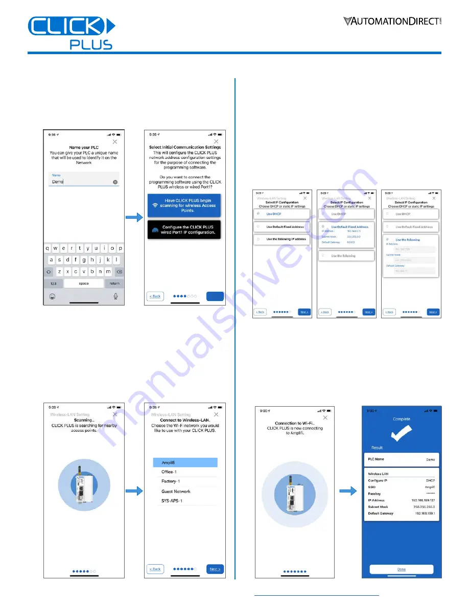
NAME THE CPU AND SELECT A PORT

6. 

Enter a name for the CPU and tap 

Next

. Choose a unique name 

if other CLICK PLCs are on your network.

7. 

Choose which network port to provision (wired or wireless).

CONNECT TO A WIRELESS ACCESS POINT  
(SKIP FOR WIRED CONNECTION)

You will need an active Network Access point available within range 
of the CLICK PLUS PLC, and know the password to allow the PLC 
to connect to the Network.

8. 

The CLICK PLC will scan for any access point within range. 
Select an Access Point and type in the correct password that the 
PLC will need to connect. 

SET UP NETWORK PARAMETERS

9. 

Once the PLC is connected to the wireless access point or wired 
network, choose which IP address configuration to use, then 
tap 

Next

 to continue.

9a. 

Use DHCP

: Automatically assign a network IP address to 

the CLICK PLUS PLC. This is often the simplest way to 
connect.

9b. 

Use Default Fixed Address

:  

Wireless: 192.168.0.11 

Wired: 192.168.0.10

9c. 

Use the following IP address

: Manually enter valid IP 

address, subnet mask, and gateway for your network.

10. 

The CLICK PLUS will connect to the network and exchange 
configuration information. If the settings are correct, the App 
will show the Completion screen and the network settings 
of the CLICK PLUS can be viewed. If using a wireless 
connection, the CLICK PLUS WLAN LED will also be ON. 

The PLC is now connected to the network and accessible to PCs 
running the CLICK Programming Software and connected to the 
same network. 

Setup & Provisioning via Bluetooth, continued

Summary of Contents for CLICK PLUS C2-03CPU

Page 1: ...or setup provisioning Click Software ver 3 00 or later PC or Click App mobile device 24VDC power supply SELV and Limited Energy CLICK power supply C0 00AC or C0 01AC is recommended Appropriate enclosu...

Page 2: ...nt may be invalidated CAUTION For use in Pollution Degree 2 Environment Use and store the equipment in an environment described in the specifications regarding temperature humidity vibrations shock et...

Page 3: ...4 pin connector located on the bottom of the CPU unit 16 28 AWG wiring is supported We recommend using crimping ferrules on all wire terminations for a more secure connection The following crimping f...

Page 4: ...module into its slot Press the module into place until it is fully seated 3 Push the top and bottom locking clips backward until they click into place Lift slightly on the locking clips until they re...

Page 5: ...SE ANT250 A remote mounted antenna is recommended to connect with the enclosure closed PREPARE A MOBILE DEVICE FOR CONNECTION Install the CLICK PLUS Provisioning App using one of the QR codes below o...

Page 6: ...need to connect SET UP NETWORK PARAMETERS 9 Once the PLC is connected to the wireless access point or wired network choose which IP address configuration to use then tap Next to continue 9a Use DHCP A...

Page 7: ...ing No Error Off Blink WLAN LED Green On Link Activity No Link Off Blink MICRO SD LED Green On Mounted Access No SD Mounted Off Blink POWER LED Green On Power Good USB Low Power Mode Power Failure Off...

Page 8: ...e 20 28 VDC Class 2 or SELV Safety Extra Low Voltage or Limited Energy Circuit power supply Maximum Power Consumption 20W Maximum Inrush Current 30A 1ms Acceptable External Power Drop Max 10ms AC Powe...

Page 9: ...bits Connector RJ12 phone jack Power Supply to HMI Supply 5V 200mA Status Lamp RX TX RS 485 Port Specifications Communications Ratings RS 485 Port Settings Baud rate 2400 4800 9600 19200 38400 57600 1...

Page 10: ...a residential area is likely to cause harmful interference in which case the user will be required to correct the interference at his own expense The C2 03CPU complies with Part 15 247 modular Inten t...

Reviews: