background image


April 28

th

, 2020 


Page 4 of 49 


General Notes 

Copyright 

 AT-Automation Technology GmbH, 1998-2020. This user guide is protected by copyright 

and all rights are reserved. No part of this document and no part of the software shall be 
reproduced, distributed, edited or translated into another language or computer 
language by any means, electronic, mechanical, photocopying, recording, or otherwise 
without consent in writing from the owners, AT-Automation Technology GmbH, Hermann-
Bössow St. 6-8, 23843 Bad Oldesloe, Germany. 

Disclaimer 

While care has been exercised in the preparation of this document to ensure that it is 
fully correct and comprehensive, the owners assume no responsibility for errors or 
omissions. Neither is any liability assumed for damages resulting from the use of the 
information contained herein. No license is granted under any patents or patent right of 
AT – Automation Technology GmbH. 

Trademarks 

All trademarks mentioned in this user guide are the property of the respective 
companies. 


Safety Instructions 

Symbols and Notes 

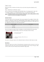
The following general safety rules must be taken into account during installation, 
operation and maintenance. Failure to do so may cause damage to the operator, the 
camera or the environment. 

 
Warning Symbols and Safety Instructions 


Warning 

Only use the system inside buildings, installations or rooms. 

Make sure that all cables are routed without risk of tripping. 

Only connect the power cord to the mains voltage after finishing the 
installation of the system. 


Summary of Contents for FebriScan

Page 1: ...April 28th 2020 Page 1 of 49 AT Automation Technology GmbH FebriScan USER GUIDE...

Page 2: ...CTIONS 6 Installation Instruction 6 Mobile Package 6 Integration Package 16 Portal Package 19 Operation 24 General Description 24 Measuring principle 24 System Start and Login 24 System Setup 25 Syste...

Page 3: ...X series products 40 Extended Warranty 40 RETURN POLICY 40 APPENDIX 42 Technichal Documentation 42 Blackbody 42 Control electronics Blackbody 43 IRSX I 44 Installation Notes 45 Step 1 Installation of...

Page 4: ...wners assume no responsibility for errors or omissions Neither is any liability assumed for damages resulting from the use of the information contained herein No license is granted under any patents o...

Page 5: ...tion regulations In case of uncertainty contact the manufacturer Caution Hot Surfaces As this device can generate temperatures above 50 C there is a risk of burning on the inside of the blackbody radi...

Page 6: ...ty of locations Its compact design allows the system to be set up and dismantled quickly The system can be easily transported in the transport case in a vehicle or shipped as required To start with th...

Page 7: ...Page 7 of 49 The first layer contains the following listed components A Calibration certificates for camera and blackbody B Monitor C Sticker and sign set D Mouse and keyboard E Blackbody with control...

Page 8: ...unit with USB C for the embedded visualization PC I Power supply unit with M12 round connector for the infrared camera J Power supply unit with USB Micro USB cable to connect the user display K User d...

Page 9: ...legs and lock them at the central locking screw Step 2 Blackbody and user display with infrared camera Mount the blackbody and the user display with the pre installed adapter pins on one of the two s...

Page 10: ...April 28th 2020 Page 10 of 49 Wing screw Central fixing screw...

Page 11: ...ending on the camera version you have purchased the distance between camera and user must be varied to cover a comparable range The following table shows the distance between camera and user Camera ve...

Page 12: ...April 28th 2020 Page 12 of 49 320mm...

Page 13: ...itable table or pedestal near the infrared camera Finally you have to set up the individual cable connections Blackbody Connect the grey cable of the control unit to the designated cable socket of the...

Page 14: ...body and follow the instructions of the system setup which is described below The user display must be switched on separately To do this press the orange button on the left side of the holding frame u...

Page 15: ...April 28th 2020 Page 15 of 49 As an alternative you have the possibility to watch the setup and initial setup of the system in the short video provided...

Page 16: ...lization of the system data at different terminals or office workstations To start with the system integration check for completeness by using the list provided in the scope of the delivery Scope of d...

Page 17: ...otected against unauthorized or accidental contact Connect the supplied power supply unit to the respective connections of the panel The pin assignment can be found in the following table Power supply...

Page 18: ...Please refer to the chapter Step 3 Positioning the tripods and floor stickers of the mobile package for the corresponding data After you have positioned all components plug all power supply units and...

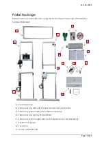
Page 19: ...pe of delivery A Mounting frame B Side panel top left with infrared camera and user monitor C Side panel bottom left with multiple socket strip D Side panel top right with blackbody E Side panel botto...

Page 20: ...nd upper side panels Position the two upper side parts in such a way that the lens of the black body and the lens of the camera are facing each other Insert the screwed in universal connectors at the...

Page 21: ...he two lower side parts according to the following illustration and put on the previously installed mounting frame with the upper side parts Insert a butt connector set at each of the mounting holes p...

Page 22: ...onics on the right side of the portal with the black body and fix the cable with Velcro fasteners along the aluminium profile Place the floor stickers in such a way that the two foot stickers are in t...

Page 23: ...s of the system setup which is described below The user display must be switched on separately To do this press the orange button on the left side of the holding frame until you get a noticeable hapti...

Page 24: ...ner of the eyelid canthus which shows the actual body temperature In combination with the high precision temperature reference the FebriScan App then verifies the detection result System Start and Log...

Page 25: ...l system variants you as the operator can decide whether all information should be made available to the user For the mobile and portal variants you also receive a user display This can be configured...

Page 26: ...Mobile Integration package Position the lens of the blackbody in such a way that the round measuring surface which you can see in the top left of the live image of the camera appears within the warm a...

Page 27: ...and the temperature below 24 C This must be ensured with external measuring devices If the values are above the specified limits perspiration in the user s facial area can falsify the detection of bod...

Page 28: ...ont of the eyes must be removed so that the inner areas of the eyes and the forehead can be seen The evaluation is performed immediately and the result is displayed on the screen for the user and the...

Page 29: ...and to switch between the display forms Operator and Customer Patient Images The system stores an image of the respective user on the camera when an increased body temperature is detected In addition...

Page 30: ...see the cameras field of view The last image captured by the camera is always displayed By clicking on the camera symbol below you have the possibility to take a snapshot This is very helpful if you w...

Page 31: ...urement parameter sets jobs or to load preconfigured ones The FebriScan system is equipped with two preset jobs which is pre activated depending on the purchased system variant Visualization and confi...

Page 32: ...uring surface for recording the temperature in the user s field of view o BB_AOI Measuring surface for recording the reference temperature of the blackbody Thresholds The threshold values required for...

Page 33: ...r a later integration of the system into a higher level control system it is possible to query the individual statuses and measured values via an industrial interface ModBus The following table lists...

Page 34: ...perly or the focus is not set correctly Adjust the camera focus with the supplied tool Otherwise contact the system manufacturer No camera image is displayed although the camera is connected and worki...

Page 35: ...perly The power supply cable has not been plugged in and the battery is empty Turn on the tablet by pressing the button on the side of the screen keep pressing until you get a haptic feedback Establis...

Page 36: ...erature resolution of the display 0 1 C Isothermal colour display with colour code temperature scale Measuring point Inner angle of both eyes Minimum detector resolution 320 x 240 Pixel Minimum covera...

Page 37: ...larm condition of at least low priority must be displayed until the camera is ready for operation message on screen Spatial resolution 1mm Pixel Emissivity 0 98 must be set Alarm Display of a physiolo...

Page 38: ...27 VDC VIL logic 0 Voltage 1 5V VIH logic 1 Voltage 3 5V Max frequency 450 kHz Digital Output 2x electrically isolated 5 24 V DC Connector Type 17 pin M12 connector shared with external power Mechani...

Page 39: ...ltage 0 to 24 VDC Power input Max 18 5W Interfaces Connector plug 7 pin male Hirschmann connection Electrical Parameters Control Unit Operating voltage 230 VDC Power input Max 20W Output voltage 0 to...

Page 40: ...is not responsible for the malfunction the warranty right is considered void This is the case if the device has been changed electrically or mechanically Especially when changing the wiring soldering...

Page 41: ...Page 41 of 49 Return address AT Automation Technology GmbH Hermann B ssow St 6 8 23843 Bad Oldesloe Germany If the system was not purchased directly from AT please contact your distributor to initiate...

Page 42: ...April 28th 2020 Page 42 of 49 Appendix Technichal Documentation Blackbody...

Page 43: ...April 28th 2020 Page 43 of 49 Control electronics Blackbody...

Page 44: ...April 28th 2020 Page 44 of 49 IRSX I...

Page 45: ...and tools for an initial commissioning are preselected Confirm your component selection by clicking on Next After the installation is finished an icon for starting the cxDiscover tool will appear on y...

Page 46: ...elivered the system contained in the Portal or Mobile Package has a defined network configuration The Ethernet contains two devices with a static network configuration Device IP Address Subnet Mask Em...

Page 47: ...ate_ap create_ap has been set up in such a way that it is automatically running as a service at system startup Change SSID WLAN Password To change the SSID the visibility of the SSID or the WLAN passw...

Page 48: ...r existing infrastructure Proceed as follows Camera Follow the steps in the section Installation instructions and open the program cxDiscover Select the camera by right clicking on the corresponding l...

Page 49: ...access point see Deactivating the access point 2 You use an additional USB WLAN stick The advantage of this procedure is that you do not need to make any changes to the existing WLAN configuration Ma...

Reviews: