


Owner Installation Instructions
GDO-10V3L2 Toro
™
17
Fig 14.1
Fig 14.2
Fig 14.3
Fig 14.4
14. Time Clock
Menu 7.3 Settings
Under this menu, three sub menus are available:
a. Run Programs. The programs of the timer can be interrupted by selecting RUN PROGRAM off.
b. Configuration Of GPI Input. General Purpose Input can be configured as OSC, PED or DST setup.
c. This is activated by the GPI input terminal with the N/O switch.
i. When GPI Selected As OSC: If the door is moving, the activation of GPI input or pressing a transmitter button with the OSC
function assigned will cause the door to stop. The next trigger will move the door in the opposite direction to the last travelled.
ii. When GPI Input Is Configured As PED: The activation of the GPI input or by pressing a transmitter button with PED function
assigned will open the door partially to allow pedestrian access but prevent vehicle access. The position the door is driven to is
automatically set to halfway during setting of the travel limits, but can be adjusted to suit.
iii. When GPI Input Is Configured As DST: GPI input can be used to switch between STD time and DST (daylight savings time). The
AUX input needs to be constantly active to show day light saving time.
14.3 Day Light Saving Time Adjustment
The time selected is the amount of time added to STD time when DST is selected by AUX input. Options are OFF, 30, 60,
90 or 120 minutes.
15. Accessories Installation
LIGHT
LOCK
LIGHT
NO
NC
COM
NO
NC
COM
SUITABLE
POWER
SUPPLY
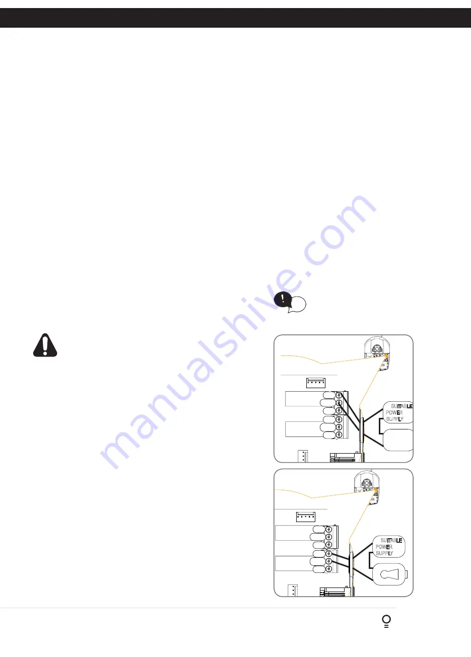
15.1 Fitting Courtesy Lights
An AC or DC courtesy light can be activated via an output on the
door opener control board. Connect the light as per the diagram.
(Fig. 15.1)
WARNING: A qualified electrician must perform the
installation where 240V AC power is used.
Menu 4. Light/Lock Times
a. Press NEXT or PREV on the wall control unit to navigate to Menu 5
Light/Lock Times.
b. Press SET to select the sub menu.
c. Press NEXT or PREV to navigate through the sub menu.
d. Press OPEN to increase or CLOSE to decrease the time.
e. Press SET to save the new time.
f. Press the STOP button two times to exit.
g. Test the light operation.
15.2 Fitting Solenoid Or Magnetic Locks
Install the lock mechanism on the door as per the manufacturers
instructions. See
Fig. 15.2
for the wiring diagram.
Menu 4. Light/Lock Times
Lock output can be programmed for both hold and pulse mode. The
operation of the lock can be programmed to activate prior to the door
and behave differently on open cycles to that on close cycles.
a. Press NEXT or PREV on the wall control unit to navigate to Menu 4
Light / Lock Times.
b. Press SET to select the sub menu.
c. Press NEXT or PREV to navigate through the sub menu.
d. Press OPEN to increase or CLOSE to decrease the time.
e. Press SET to save the new time.
f. Press the STOP button two times to exit and test the locks operation.
LIGHT
LOCK
LOCK
NO
NC
COM
NO
NC
COM
SUITABLE
POWER
SUPPLY
Fig 15.1
Fig 15.2
HELPFUL TIP: To access the PREV,
NEXT and SET buttons, unscrew the
screws at the bottom of the logic
console cover and remove cover.
tip


