51
Instructions for the installer
5.5 - SPECIAL FUNCTIONS
5.5.1 - OVERHEATING (see Step 5, on page 47)
The wood fired boiler with manual loading is subject to the thermal inertia phenomena which can cause transitional overheating
periods which have to be contained as much as possible before the intervention of the manual reset safety thermostat.
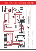
For this purpose the panel, code 23577, is predisposed for the connection and control of a heat discharge pump via the
terminals MAXP. If the boiler temperature (Tc), in spite of the fan turning off, exceeds the value of 89°C, the heat discharge pump
is activated and remains running until this temperature falls below 86°C.
If the installation is not equipped with a heat discharge pump, the jumper between the MAXP and MKP terminals(see paragraph
5.3 - on page 48) must not be removed; this jumper has in fact the purpose of feeding the C.H. pump even if the room thermostat
(TAMB) is open; this could involve an unrequested heating of the radiators even if the ambient conditions apparently do not
require it.
If the installation is equipped with an accumulator (see paragraph 3.12) the thermal inertia will have to be discharged
through the recirculation pump KKP and therefore it is necessary that the above mentioned jumper is placed between
the MAXP and KKP phase.
Obviously in order to allow any thermal discharge via the heating system, it is necessary that
there are no closed gate valves between the boiler’s flow and return connections.
5.5.2 - COMBUSTION GAS TEMPERATURE CONTROL
(only in case of connection to a single chimney)
For this possibility, check local requirements and rules in force.
In case of flue evacuation in a chimney serving the wood fired boiler and a back-up oil fired boiler (a gas fired boiler needs its
own chimney), it is possible to fit a flue thermostat, in the part of the chimney serving only the wood fired boiler, connected to the
AGW terminals, in order to stop the burner firing in case the flue temperature of the wood fired boiler, is over 100°C.
5.5.3 - FAN OVERHEATING PROTECTION SYSTEM
In this range of boilers (GASOGEN G3 2S) this system is not activated.
5.5.4 – TEMPERATURE SENSOR FAILURE ALARM (note for After Sales Service)
If the flow sensor (Tc) malfunctions or is not correctly connected to the relative terminals, the microprocessor’s logical co ntrol
activates the acoustic-visual alarm, made up of a LED and a BUZZER, in a continuous mode: if the problem persists, consult the
After Sales Service.
The installation of a heat storage tank (see paragraph 3.12) foresees the connection of the return sensor (Tr) to the dedicated
terminals: to gain access to the previously described alarm service for the Tr sensor, it is necessary that the After Sales Ser vice,
during the installation stage, removes the jumper placed between the pins 71 and 72; if not, the alarm for the Tr sensor malfun ction
is inhibited: the manufacturer declines any responsibility.
If the above indicated malfunctions occur, the recirculation pump (KKP), the C.H. pump (MKP) and the heat discharge pump
(MAXP) will be activated, the fan will be turned OFF and the automatic or manual transition to the auxiliary boiler will be
prevented.
The temperature sensor is a NTC resistor. To check that it is in good working condition keep the
following values in consideration:
MEASURED TEMPERATURE
RESISTANCE
MEASURED TEMPERATURE
RESISTANCE
0 °C
33242 Ohm
50 °C
3548 Ohm
10 °C
19947 Ohm
55 °C
2945 Ohm
15 °C
15659 Ohm
60 °C
2459 Ohm
20 °C
12394 Ohm
65 °C
2063 Ohm
25 °C
9888 Ohm
70 °C
1740 Ohm
30 °C
7947 Ohm
75 °C
1475 Ohm
35 °C
6433 Ohm
80 °C
1256 Ohm
40 °C
5242 Ohm
85 °C
1075 Ohm
45 °C
4300 Ohm
90 °C
923 Ohm
Summary of Contents for Gasogen
Page 1: ...Wood Fired Boiler Gasogen 29 93kW Installation and Servicing Manual ...
Page 66: ...Gasogen notes ...
Page 67: ...notes ...

