18
Instructions for the installer
B
DETTAGLIO B
B
DETTAGLIO B
1
4
5
6
3
2
7
9
8
2
1
3
7
5
4
6
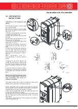
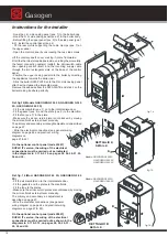
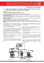
fig. 14
- Hook the L.H. side casing panel (pos. 1) to the boiler body.
- Hook the R.H. side casing panel (pos. 2) to the boiler body.
- Before fitting the upper panel (pos. 3) to the side panel (pos.1
& 2), install the control panel (pos. 4).
- Fit the rear profile supporting the cable clamps (pos. 7).on
the upper panel
- Open the control panel by unscrewing the two side screws.
Lift the control panel’s cover, making it rotate frontwards.
Fit all the thermostat capillaries inside, unrolling them carefully,
the fan(s) connecting cable(s) (outlet), the microswitch cable
door opening control (inlet), and the incoming supply cable
through the two rectangular slots on the base of the control
panel.
- Position the upper casing panel onto the boiler by directing
the capillaries towards the boiler rear.
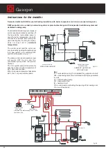
- Stick the boiler DATA PLATE onto the R.H. side casing panel
after having cleaned the interested area.
Remove the adhesive from the DATA PLATE and stick it on the
boiler making it adhere perfectly.
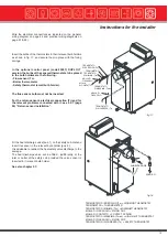
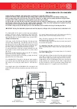
fig. 15
Ref. fig.15 (Models GASOGEN G3 25 2S, GASOGEN G3 40
2S, GASOGEN G3 50 2S)
- Fit the air manifold (pos. 1) on to the intermediate door.
- Fit the gasket (pos. 4) and the plate (pos. 5) to the manifold.
- Fit the fan (pos. 7) to the plate.
- Make sure the air non-return plate is not blocked, by moving
the air manifold’s external lever manually.
The primary and secondary air draught adjustment is described
on page 57.
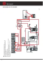
- Wire the electrical connections (see general wiring
diagram on page 44 and practical wiring
diagrams on
page 21 & 22).
On the optional control panel (code 23557)
DUPLO IT version, the wiring of the electrical
connections must be carried out as indicated
in the diagrams in 3.11 & 3.12, on pages 24, 26, 29, 31, 33,
36 and 39.
Models: GASOGEN G3 25 2S
GASOGEN G3 40 2S
GASOGEN G3 50 2S
Models: GASOGEN G3 65 2S
GASOGEN G3 80 2S
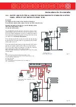
Ref. fig. 16 (Mod. GASOGEN G3 65 2S, GASOGEN G3 80
2S)
- Fit the air manifolds on to the intermediate door.
- Fit the gaskets and the plates to the manifolds.
- Fit the fans to the plates.
- Make sure the air non-return plates are not blocked, by moving
the air manifold’s external lever manually.
The primary and secondary air adjustment is
described on page 57.
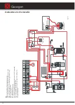
- Wire the electrical connections (see general
wiring diagram on page 44 and practical wiring
diagrams on page 21 & 22).
On the optional control panel (code 23557)
DUPLO IT version, the wiring of the electrical
connections must be carried out as shown in the
diagrams in 3.11 & 3.12, on pages 24, 26, 29, 31,
33, 36 and 39.
fig. 16
DETAIL B
DETAIL B
Gasogen
Summary of Contents for Gasogen
Page 1: ...Wood Fired Boiler Gasogen 29 93kW Installation and Servicing Manual ...
Page 66: ...Gasogen notes ...
Page 67: ...notes ...

