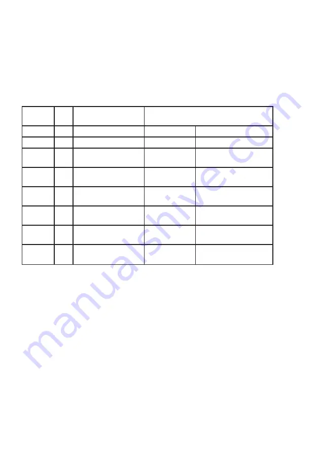
AutoAnchor AA702 Owner'S Manual Download Page 14

13

AA702

Terminal

Default Function
Assignment

Alternative Function Assignment

BATT     (-)

Ground

BATT

(+)

Positive

OUT 1

(+)

1  

Windlass 

  Down

Power Enable when 

dual thrusters selected

OUT 2

(+)

1  

Windlass

   Up

OUT 3

(+)

Thruster A (Bow)

   Port

Windlass

Option A

OUT 4

(+)

Thruster A (Bow)

  Starboard

Windlass 

Option B

OUT 5

White

(+)

Thruster B (Stern)

  Port

Power Enable

3

 Rope/Chain

  Motor Load Wires

OUT 6

Brown

(+)

Thruster B (Stern)

  Starboard

Dual Speed

3

 Rope/Chain 

  Motor Load Wires

2.4.1 BASE STATION INTERNAL CONNECTIONS

Notes:

Unused outputs are automatically assigned as auxiliary outputs.  See Pages 25 and 29 

for more details.  All outputs are active high (+).

1

 Only one windlass can be connected to a base station.  2 windlasses require 2 base 

   stations. The windlass outputs OUT1 and OUT2 are fixed,  however, the     

   control buttons for up and down can be swapped in the set up menu as can the 

   location of the windlass (bow or stern).

2

 Stern and bow thruster output locations stated are the default locations.  These can   

   be swapped in the set up menu. The port and starboard directions for each output 

   cannot be changed.

3

 Only required for rope/chain counting

   OUT 5 = White Motor Load Wire

   OUT 6 = Brown Motor Load Wire

The AA710 kit has one master base station and one remote console.  

Each base station has 6 outputs. Up to 2 slave stations can be attached to the master 

station to provide extra outputs.

2.4 REMOTE CONSOLE AND BASE STATION INSTALLATION

Summary of Contents for AA702

Page 1: ......

Page 2: ... printing However the AutoAnchor products are continuously being reviewed and improved and product specifications may be changed without notice The latest product specifications may not be reflected in this version of the manual The documentation relating to the AutoAnchor products is created in the English language and may be translated from English to another language In the event of any conflict be...

Page 3: ...re set windlass profile lists wiring diagrams the Owner s Manual and the Quick User Guide All documents must be left on board for the owner Non compliance with the instructions could impair operation of the AA710 the windlass thruster or other equipment and could result in personal injury and or damage to the boat Non compliance with the instructions will negate the manufacturer s warranty The AA71...

Page 4: ...67 IP67 Operating Temperature Range 23o F to 140o F 5o C to 60o C 23o F to 140o F 5o C to 60o C Wireless Transmission 2 4GHz ISM Band IEEE 802 15 4 Compliant 64 Bit Unique ID Wireless Range Typical Minimum 10m 30ft Range depends on installation Outputs 6 System Supports Up to 3 base stations and 3 consoles Rode Chain Only Stainless or galvanised steel Rode Rope and Chain Must have a minimum of 10f...

Page 5: ...evice complies with CFR47 Part 15 of FCC Rules for Class B equipment ESTI Information CE This device meets the relevant standards set out in European Standard EN 60945 2002 for maritime navigation and radio communication equipment and systems These standards are intended to provide reasonable protection against interference by other emission generating products on the boat Compliance with these st...

Page 6: ...ce the sensor Magnet Seal Insert the magnet into the hole and cover it with a minimum of 1mm of epoxy to protect it against corrosion See Fig 1 on page 8 Magnet Size and Position Refer to the instructions for your specific windlass type 2 1 3 SENSOR INSTALLATION OVERVIEW Vertical Windlasses The sensor is fitted in the deckplate Some deckplates are predrilled for the sensor Others have a dimple or ma...

Page 7: ...503 25 m 82 ft Part 9504 35 m 114 83 ft Part 9514 A 2m male female cable Part 9505 plus a gender changer Part 9510 will be required to connect the extension cable to the base station Field Connectors Sensor Connection The sensor is plugged direct into the AA702 base station Do not leave the cable hanging loose it must be tied in place with cable ties Extension cable gender changers and field connec...

Page 8: ... of 5mm This sensor requires a field connector The AutoAnchor will operate with a reed switch sensor for all chain rode If using combination rope and chain rode the reed switch sensor provides a reasonably accurate count of rode deployed but on retrieval the display may be incorrect because it cannot allow for the stretch in the rope For an accurate rope and chain count the reed switch sensor shoul...

Page 9: ...hainwheel Deckplate Refer to the Overview Notes on page 5 before starting installation Sensor Connection Ideally the sensor should be plugged directly into the AA702 base station If longer cable is required use the AA 2m male female extension cable Part 9505 or one of the AA standard male male extension cables plus the 2m cable and a gender changer Ensure the connectors are firmly screwed together ...

Page 10: ...sensor position range at the stern end of the windlass See Fig 5 It must also be aligned with the magnet so that the rode passes between the sensor and the magnet The centre of the magnet and the centre of the sensor may be up to 10mm out of direct alignment See Fig 3 The gap between the sensor and magnet must be as per the table below Chainwheel Deckplate Fig 3 Sensor Magnet may be up to 10mm out...

Page 11: ...sensor to the AA702 base station Ensure the connectors are firmly screwed together See the information on page 6 Loose cable should be tied in place with cable ties and kept clear of chain Refer to the Overview Notes on page 5 before starting installation It is not possible to set out a single installation method for horizontal windlasses 7KH VHQVRU PD EH WWHG LQVLGH WKH ZLQGODVV RU RX PD QHHG D VH...

Page 12: ...ch turns Magnet Installation Size 10mm x 8mm magnet 9061 The magnet can be mounted on the main shaft or on the side of the drum See Figs 8 and 9 If mounted on the side of the drum position it close to the inside to reduce the peripheral speed of the magnet Fix the magnet into position with epoxy ensuring it is completely sealed to prevent corrosion Sensor Installation The Grey 3 wire AA sensor 906...

Page 13: ...eller can also cause serious damage to the motor I WKH WKUXVWHU VWRSV JLYLQJ WKUXVW ZKLOH WKH PRWRU LV UXQQLQJ WXUQ LW RII immediately 2 2 1 POWER ENABLE SETTING This is used to activate a power pack It will time out and switch off after the delay time selected 2 3 INSTALLATION TO OPERATE AUXILIARY EQUIPMENT Outputs from the AA710 can be connected to control auxiliary equipment on the vessel such ...

Page 14: ...outputs are active high 1 Only one windlass can be connected to a base station 2 windlasses require 2 base stations The windlass outputs OUT1 and OUT2 are fixed however the control buttons for up and down can be swapped in the set up menu as can the location of the windlass bow or stern 2 Stern and bow thruster output locations stated are the default locations These can be swapped in the set up men...

Page 15: ...ti core cable must be used and the base station must be mounted so that the cables extend below the unit ZKHQ HG WR WKH ZDOO the lid can be removed easily during operation the LED indicators can be seen during operation the best reception is available see Fig 10 the cables extend below the unit when fixed to the wall to avoid condensation entering through the cable gland Cradle Loop for Lanyard Cov...

Page 16: ...oAnchor devices Power supply must not be from the motor positive near the windlass 2 5 2 MULTIPLE BASE STATION INSTALLATIONS The master base station must be powered up when using a slave base station application Separate base stations may be powered from separate supplies however if 2 products are connected to the same base station they must be powered by the same supply or relays must be used as ...

Page 17: ...ass a thruster or auxiliary equipment Outputs 5 and 6 can be used for other options Interlock protection is included in the system Do not fit diodes or interlock devices to outputs as these will prevent the system from operating correctly All battery and motor cables must be ring type insulated to prevent short circuits and installed no closer than 1ft 300mm away from the sensor head To reduce the ...

Page 18: ...y sensor cable information 2 7 5 CONNECTING THE CABLES INTO THE BASE STATION Remove the lid from the AA703 base station Feed the multi core cable through the waterproof gland Connect the cables to the terminal block using a screwdriver to press down and open each terminal as required See the photograph below Tighten the cable gland Replace the lid 2 7 3 CONNECTION TO LOW CURRENT DRIVES When connec...

Page 19: ...red to each other to operate the system If extra outputs are required up to 2 additional base stations known as slave stations may be added into the system Up to 4 consoles can be registered to operate a system Follow the instructions to register the consoles and base stations 3 2 WIRELESS INTERFACE SET UP 3 2 2 REGISTRATION SWITCH Located inside the base station Use to register the base station t...

Page 20: ...ystem functions 8 If you have more than 1 console to register to the base station repeat the steps above ensuring the first console is turned off before you start 9 When finished replace the lid on the base station 3 2 6 TO TURN THE AA710 REMOTE CONSOLE OFF AFTER REGISTRATION Press the left arrow to escape from Setup to the default start up screen Press the Mode button to display the menu Scroll to ...

Page 21: ...efore replacing the lids on the base stations you need to record the unique ID number for each base station The ID is on the white label next to the registration switch This number is the same as the last 4 digits on the bar code label on the outside of the base station Master Base Station ID ______________ Slave Station 1 ID ______________ Slave Station 2 ID ______________ Note The AA710 console ...

Page 22: ... a new product 3 2 9 REGISTERING A PREVIOUSLY USED BASE STATION OR CONSOLE ALL SETTINGS MUST BE CLEARED Previously Used Base Station Turn off all existing base stations and consoles Turn on the power to the used base station only Hold down the registration button for 15 seconds until all three LED s flash This indicates the base station has performed a complete factory reset and all settings have r...

Page 23: ...on Bow Stern Auxiliary Aux A D Power enable Off delay GENERAL Language Units Feet Meters Fathoms Key beep Auto off time 1 20 min 3 3 SET UP MENU OVERVIEW The AA702 base station must be powered up and the AA710 remote console must be turned off to access the Set up Menu Note If you have more than one AA710 remote console ensure only one unit is switched on during setup or when changing settings The...

Page 24: ...Menu and press again to return to the Start Screen Do not use this setting unless you need to select a clear channel to avoid interference Turn OFF all consoles prior to commencing this Channel changing should only be carried out close to the base station The procedure can take up to 20 seconds to complete It may take two attempts to select the new channel If contact with the base is lost try agai...

Page 25: ... 2 The outputs are operated using the up and down buttons 3 5 1 2 Windlass Options Outputs 3 and 4 Option A and B can be used from the Windlass page for functions associated with anchoring For example decklights deck wash anchor stow power cleat Option A is operated using the left arrow button and controls Output 3 Option B is operated using the right arrow button and controls Output 4 Both option...

Page 26: ...l other systems Power Enable Off Delay Default 5 minutes The Off Delay is adjustable from 0 60 minutes Adjust to your requirements Access Power Enable through the Modes menu Select Modes in the Set Up Menu Select the AA702 ID eg 803D The screen will show the Modes menu Select Power enable Select Off delay Adjust the Off delay time to meet your requirements Save and press 3 times to return to the S...

Page 27: ...nal Default Function Assignment Alternative Function Assignment BATT Ground BATT Positive OUT 1 1 Windlass Down Power Enable when dual thrusters selected OUT 2 1 Windlass Up OUT 3 2 Thruster A Bow Port Windlass Option A OUT 4 2 Thruster A Bow Starboard Windlass Option B OUT 5 White 2 Thruster B Stern Port Power Enable 3 Rope Chain Motor Load Wires OUT 6 Brown 2 Thruster B Stern Starboard Dual Spee...

Page 28: ...urn to Modes Select Power enable Select Off delay Adjust the Off delay time to meet your requirements Press 3 times to return to the start screen Modes 803D EXAMPLE 1 A windlass Option A anchor light and Option B manual anchor wash This set up uses a single AA702 base station Select Modes In the Set Up Menu Select the AA702 ID eg 803D The screen will show the Modes menu Windlass Select Windlass Se...

Page 29: ... thruster Return to Modes Power Enable has already been set up for both thrusters Press 3 times to return to the start screen Optional and Auxiliary Functions Still Available are Base Station 803D Output 6 Auxiliary Base Station 815A Output 3 Option A or Auxiliary Output 4 Option B or Auxiliary 815A 803D 803D 815A EXAMPLE 3 Two dual speed windlasses Option A anchor light auto wash This set up uses...

Page 30: ... the AA702 ID eg 803D The screen will show the Modes menu Windlass Follow the steps in example 1 above for the windlass settings Return to the Modes screen Auxiliary Equipment Select Auxiliary outputs The screen displays the Auxiliary Outputs available In this example there are 2 auxiliary outputs Both ouputs are currently disabled Select the Auxiliary Output to set up eg Output 3 The screen shows...

Page 31: ...g retrieval when the windlass will stop Complete retrieval using manual operation Scroll to Docking distance Select docking distance Increase or decrease the docking distance Save and return to Windlass Setup Setting 3 6 4 SET RODE Scroll to Rode Select Rode Select Chain only or Rope and chain and follow the instructions below to enter the settings for the rode selected 3 6 3 SET TOTAL RODE LENGTH...

Page 32: ...n the chainwheel as a guide turn the chainwheel one complete turn causing the chain to be released on to the deck Step 6 Measure the length of chain from the mark on the deck to the mark on the chain Step 7 Enter this measurement See below 3 7 1 CHAIN PER TURN 3 7 CHAIN ONLY RODE SET UP Select Chain per turn Enter the measurement In mm or in metric inches depending on units selected See the table ...

Page 33: ...er information for the chain and rope per turn See the instructions below This is the length of chain that is released during one complete turn of the chainwheel The chain per turn for some windlasses is listed in Appendix 1 If your windlass is not listed follow the instructions on page 31 to calculate the chain per turn 3 8 2 CHAIN PER TURN FOR ROPE AND CHAIN RODE 3 8 3 TO ENTER THE CHAIN PER TUR...

Page 34: ...asurement See below Setting Chainwheel Mark Chain Mark Deck Mark Distance to Measure 3 9 DRUM WINCH SET UP Access via the Windlass Set Up Menu 3 settings are required Total Rode Length Inside Diameter Outside Diameter with rode retrieved Turn the AA710 remote console off Hold together to access the Set up menu Scroll to Windlass Select Windlass 3 9 1 TO ACCESS THE WINDLASS SET UP 3 9 2 SET TOTAL R...

Page 35: ...SWAP CONTROLS Default setting Up and Down Some operators prefer to use these buttons so that Out and In Access the swap controls feature via the Windlass Set up Menu Turn the AutoAnchor Off Hold together to access the Set up menu Select Windlass Select Swap Controls Exit to the Set Up Menu or press again for the start screen Note This feature can not be used to correct wiring errors Select Inside ...

Page 36: ... 2 TO TURN THE AUTO ANCHOR OFF In the start screen press the Mode button to display the menu Scroll to Off Select Off OR Press and hold the MODE button for 6 seconds Note Note The AA710 remote console automatically turns off after a preset time with out use Default Auto Off is 5 minutes The Auto Off Time can be changed to between 4 and 20 minutes in the Setup menu See page 23 Mode On Off Turn on H...

Page 37: ...CAUTIONS It is the owner s sole responsibility to ensure the AutoAnchor is installed used and maintained in a manner that will not cause accidents personal injury or property damage When using the AutoAnchor the operator must follow safe boating practices for all equipment use DOO HTXLSPHQW FRQWUROOHG E WKH XWR QFKRU PXVW EH LQVWDOOHG DQG XVHG VWULFWO according to the original equipment manufactur...

Page 38: ...ng instructions or the use of the AutoAnchor in a way that may cause accidents or damage or that may violate the law 4 5 WINDLASS OPERATION WITH THE AA710 Installation and set up must be complete and the anchor must be docked before starting this process Clear the AutoAnchor to zero if necessary See page 40 Deploy the anchor using the AutoAnchor Initially the status bar will display Sensor tuning ...

Page 39: ...M During retrieval the windlass will stop and the AA710 beeps to warn the operator the anchor is at the preset docking distance Press and hold the button to continue retrieval If the system has been set up for dual speed It will change to slow at this point Extra care must be taken at this stage of retrieval Use the Automatic Function to Preset the length of rode for deployment Have hands free ope...

Page 40: ... up or down to the value Save and return to start screen To disable automatic operation Set the rode to be released value to Off 4 5 4 2 Enable Automatic Operation A rode to be released value must be entered to use automatic operation 4 5 4 5 Retrieve the Anchor Using Automatic Operation Turn the AA710 on Clear the safety lock Press the Mode button to enter the Menu Press the Mode Button again to ...

Page 41: ...ust be turned on Press to access the Menu Scroll to Clear to Zero Select Clear to zero Select No Yes Yes return to start screen No return to the menu then press again to return to the start screen 4 6 USING DUAL SPEED You must have a windlass with a dual speed motor to use this feature Default Speed is slow Use the right arrow to toggle between fast and slow speed The current speed is displayed on...

Page 42: ...rer s instructions and with the appropriate safety precautions The thruster must not be operated close to swimmers the powerful suction of water could cause serious injury Never run the thruster out of the water as this can seriously damage the motor Running a thruster without resistance from the propeller can also cause serious damage to the motor If the thruster stops giving thrust while the mot...

Page 43: ...ration to port and starboard 4 9 5 COMBINED BOW AND STERN THRUSTER OPERATION Bow and stern thrusters selected System powered up and idle Bow and stern thrusters to port Bow and stern thrusters to starboard Bow thruster selected System powered up and idle Bow thrusting to port Bow thrusting to starboard Stern thrusting to starboard Stern thrusting to port Stern thruster selected System powered up a...

Page 44: ...1 second For example Hold the Up button for more than 1 second to change to Pivot Mode Use the left or right buttons to turn the boat clockwise or anticlockwise To exit pivot mode and return to single thruster operation press the up or down button Press the up button to return to bow thruster operation Press the down button to return to stern thruster operation Clockwise Anticlockwise ...

Page 45: ... The AA710 remote console automatically turns off after a preset time without use Default Auto Off is 5 minutes The Auto Off Time can be changed from between 4 to 20 minutes in the Setup menu See page 23 OR Tap to access the Menu Scroll to Select Mode Select Select Mode Scroll to Auxiliary outputs Select Auxiliary outputs On the console use the key shown on the screen to operate the Auxiliary outp...

Page 46: ... battery indicator shows the battery level is low Do not allow the battery level to fall to zero Two alkaline AA 1 5V batteries are required Turn off the console and turn off the power to the base station Open the console case by removing the screws and lifting off the back cover Remove the used batteries and replace them with new batteries in the same position Check that the perimeter seal is cle...

Page 47: ...d chain settings See message 7 below 3 The load sensing wires are not connected for rope chain counting See the rope chain wiring diagram and message 7 below 4 A solenoid wire is disconnected See message 9 below 5 No rode to be released value has been entered See page 39 6 Total rode set to OFF See page 30 2 Battery voltage too low to operate windlass The voltage displays on the status bar 1 If th...

Page 48: ...own in manual mode when this message is displayed The count will not be accurate APPLIES TO ROPE CHAIN SYSTEMS ONLY 1 Check the correct windlass set up has been selected See page 30 2 Check magnet and sensor installation is correct The grey AA sensor must be installed for rope chain counting The magnet must be installed in the top of the chainwheel and the sensor must be fitted as per figure 5 on pa...

Page 49: ...ning the console or base station If the problem persists 4 The registration may be incorrect Clear registration settings for all consoles and base stations see page 18 Try registration again Check if the base station or console is close to severe interference eg VHF radios modified sine ware inverters cable and antennas or radar antennas 5 Try setting to another channel See page 23 6 If connection ...

Page 50: ...indicator arrow is still pulsing this is not a fault The rode is changing from rope to chain 5 The count stays on zero when rode is deployed and counts out when rode is retrieved The unit is not receiving correct direction information Solenoid up and down wires are swapped 6 Windlass deploys when the Up button is pressed and retrieves when the Down button is pressed 1 The motor or solenoid wiring ...

Page 51: ... Signal C Minimum value is 100 mV when reading the chain pulses AA Black Sensor Chain Only Set Up Bottom Fit Magnet South pole must face sensor Signal A Red sensor wire from the console moves between 2 6V and 4 6V Minimum working signal 0 5V Signal B Reading is not relevant Signal C Reading is not relevant Reed Switch Chain Only Set Up Bottom Fit Magnet Polarity not relevant Signal A Red sensor wi...

Page 52: ... Up Solenoid 10 7 V 5 6 V Sensor Installation Diagnostic Messages These messages appear when the AA710 is turned on Go to the extended diagnostics for more information After fixing the sensor installation retune the sensor See page 37 Red sensor wire grounded The Red sensor wire is overloaded below 2 5 volts Disconnect the plugs one at a time to locate the short or excessive load If no short is fou...

Page 53: ...mm 295 mm 11 6 inches HRC 6 or HRC 8 6062 3 1 4 7 mm 300 mm 11 8 inches HRC 8 6074 5 8 mm 290 mm 11 4 inches HRC 8 6086 7 5 16 310 mm 12 2 inches Liberty 5220 P101525 3 8 10 mm 330 mm 13 0 inches Liberty 5346 P101542 5 16 360 mm 14 2 inches Liberty 5443 P101547 8 mm 340 mm 13 4 inches RC10 P103309 3 8 10mm 322 mm 13 01 inches Windlass Model Chainwheel Reference Chain Size Chain per Revolution Atla...

Page 54: ...6 8 mm 9 16 14mm 127 Lewmar V3 1000W 12 002 3 8 9 5mm 9 16 14mm 124 Lewmar V3 1000W 12 002 5 16 8 mm 9 16 14mm 117 Lewmar V700 320W 12 765 670 1 4 7mm 1 2 12mm 130 Lewmar V700 320W 12 670 1 4 6mm 1 2 12mm 130 Lewmar Pro Series 700 500W 12 762 1 4 7mm 5 8 16mm 131 Windlass Model Chainwheel Chain Size Rope Size AutoAnchor Reference Dorado 7mm 14mm 65 Dorado 7mm 12 mm 66 Project 1000 1000W 916b 5 16 ...

Page 55: ... HRC 8 6086 7 5 16 12 mm 3 strand 29 HRC 8 6086 7 5 16 12 mm 8 plait 30 HRC 8 6086 7 5 16 9 16 14 mm 3 strand 31 HRC 8 6086 7 5 16 5 8 16 mm 3 strand 32 Liberty 1000 Watt 5220 P101525 3 8 10 mm 20 mm 3 strand 7 Liberty 1000 Watt 5220 P101525 3 8 10 mm 20 mm 8 plait 8 Liberty 1000 Watt 5346 P101542 5 16 5 8 16 mm 3 strand 5 Liberty 1000 Watt 5346 P101542 5 16 5 8 16 mm 8 plait 6 Liberty 1000 Watt 5...

Page 56: ...nd 89 Atlantic 2200 12 24V 112 3 8 10 mm 5 8 16 mm 3 strand 87 Atlantic 2500 12 24V 57 5 16 8mm 5 8 16 mm 3 strand 90 Atlantic 2500 12 24V 60 3 8 10 mm HT 3 4 19 mm 3 strand 92 Atlantic 2500 12 24V 61 3 8 10 mm BBB 3 4 19 mm 3 strand 93 Atlantic 2500 12 24V 114 1 2 12 5mm 7 8 22mm 3 strand 94 Atlantic 2500 12 24V 119 3 8 10 mm 3 4 19 mm 3 strand 97 Atlantic 2500 12 24V 121 5 16 8 mm 5 8 16 mm 3 st...

Page 57: ... Check out the collection of anchors and docking we offer ...

Reviews: