


User’s Manual – 400E Series
Page 4
DCU 410E
Operation
Configurations
The behavior of the DCU 410E
depends heavily on its configuration.
For instance, the start/stop buttons
can be configured as latched, meaning
the DCU completes the start/stop
cycle once the button is pressed, or it
can be configured as hold-to, meaning
the operator must keep the button
pressed until the engine has started or
stopped.
The configuration of the DCU is not
part of this document.
Buttons
The DCU has ten buttons for the
following:
Engine Start
Engine Stop
Display/Hide Alarm List
Display/Hide Menu
Menu navigation with arrow
up/down
Four “softbuttons” with screen-
dependent functionality
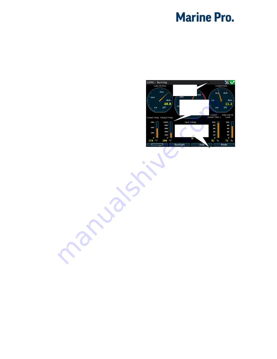
Screen Layout
The screen is divided into three main
sections from the top and downwards
as follows:
Status bar
Top-most line on the screen, which is
reserved for engine state (left) and
status symbols (right).
The status bar flashes in the event of
an alarm.
Main screen area
This is where all instruments and
menu items are displayed.
Softbutton bar
Bottom-most line on the screen, which
is reserved for softbuttons.
These have varying functionality
depending on the current screen.
Status bar
Main screen
area
Softbutton bar


