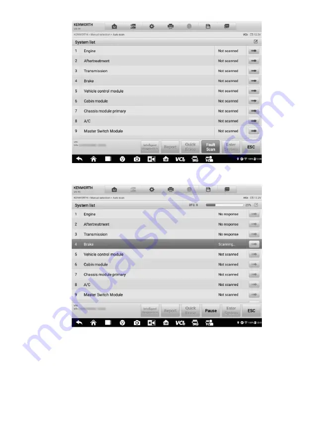
background image

69 


Figure 5-4 

Sample Fault Scan on System List Screen 1 


Figure 5-5 

Sample Fault Scan on System List Screen 2 

2) 

On the 

Topology

 screen, a system with identified faults will display in orange, with 

the  number  of  faults  displayed  on  the  upper-right  corner  of  the  system  icon.  The 
number of total faults will display on the top. 

Summary of Contents for MaxiSys MS909CV

Page 1: ...on the latest information available at the time of printing Autel reserves the right to make changes at any time without notice While information of this manual has been carefully checked for accuracy no guarantee is given for the completeness and correctness of the contents including but not limited to the product specifications functions and illustrations Autel will not be liable for any direct ...

Page 2: ...safety of others in the work area the device being used or the vehicle being tested Before using the device always refer to and follow the safety messages and applicable test procedures provided by the manufacturer of the vehicle or equipment being tested Use the device only as described in this manual Read understand and follow all safety messages and instructions in this manual Safety Messages S...

Page 3: ...attended while testing Be extra cautious when working around the ignition coil distributor cap ignition wires and spark plugs These components create hazardous voltages when the engine is running Keep a fire extinguisher suitable for gasoline chemical and electrical fires nearby Do not connect or disconnect any test equipment while the ignition is on or the engine is running Keep the test equipmen...

Page 4: ...n 3 2 1 2 Power Sources 5 2 1 3 Technical Specifications 6 2 2 MAXIFLASH VCI 8 2 2 1 Functional Description 8 2 2 2 Power Sources 9 2 2 3 Technical Specifications 10 2 3 MAXIBAS B200 11 2 3 1 Functional Description 11 2 4 ACCESSORIES KIT 12 2 4 1 Main Cable 12 2 4 2 Non OBDII Adapters 12 2 4 3 Other Accessories 13 3 GETTING STARTED 16 3 1 POWER UP 16 3 1 1 Application Buttons 17 3 1 2 Locator and ...

Page 5: ...ONS 52 4 10 PROGRAMMING AND CODING 54 4 10 1 Coding 55 4 10 2 Reprogramming 55 4 10 3 Re flash Errors 56 4 11 GENERIC OBDII OPERATIONS 57 4 11 1 General Procedure 57 4 11 2 Function Descriptions 58 4 12 DIAGNOSTICS REPORT 61 4 12 1 Pre Scan and Post Scan 61 4 12 2 Diagnostic Report PDF 61 4 13 EXIT DIAGNOSTICS 65 5 INTELLIGENT DIAGNOSTICS 66 5 1 ACCESSING INTELLIGENT DIAGNOSTICS 66 5 1 1 Auto Scan...

Page 6: ...ect the Battery Tester 81 7 2 IN VEHICLE TEST 83 7 2 1 Start the test 83 7 2 2 Battery Test 84 7 2 3 Starter Test 86 7 2 4 Generator Test 87 7 3 OUT VEHICLE TEST 88 7 3 1 Test Procedure 88 7 3 2 Test Results 89 8 MULTIMETER 91 8 1 SAFETY INFORMATION 91 8 2 CONNECTING THE MULTIMETER 92 8 3 SCREEN LAYOUT AND OPERATIONS 93 9 SETTINGS 96 9 1 UNIT 96 9 2 LANGUAGE 96 9 3 PRINTING SETTINGS 97 9 4 NOTIFIC...

Page 7: ...1 2 VCI CONNECTION VIA BLUETOOTH 111 11 3 BAS CONNECTION VIA BLUETOOTH 112 11 4 VCI UPDATE 113 11 5 BAS UPDATE 114 12 UPDATE 115 13 SUPPORT 117 13 1 PRODUCT REGISTRATION 117 13 2 SUPPORT SCREEN LAYOUT 117 13 3 MY ACCOUNT 118 13 3 1 Personal Info 118 13 3 2 Update Info 118 13 3 3 Service Info 119 13 4 TRAINING 119 13 5 DATA LOGGING 119 13 6 FAQ DATABASE 120 14 MAXIVIEWER 121 15 MAXIVIDEO 123 15 1 A...

Page 8: ...FEEDBACK 132 19 MAINTENANCE AND SERVICE 133 19 1 MAINTENANCE INSTRUCTIONS 133 19 2 TROUBLESHOOTING CHECKLIST 133 19 3 ABOUT BATTERY USAGE 134 19 4 SERVICE PROCEDURES 135 19 4 1 Technical Support 135 19 4 2 Repair Service 136 19 4 3 Other Services 136 20 COMPLIANCE INFORMATION 137 21 WARRANTY 138 21 1 12 MONTH LIMITED WARRANTY 138 ...

Page 9: ...such as buttons and menu options Example Tap OK 1 2 1 Notes and Important Messages Note A NOTE provides helpful information such as additional explanations tips and comments Example NOTE New batteries reach full capacity after approximately 3 to 5 charging and discharging cycles Important IMPORTANT indicates a situation that if not avoided may result in damage to the tablet or vehicle Example IMPO...

Page 10: ...ting screen may vary for each vehicle being tested Observe the menu titles and on screen instructions to make correct option selection 1 2 4 Procedures An arrow icon indicates a procedure Example To use the camera 1 Tap the Camera button The camera screen opens 2 Focus the image to be captured in the view finder 3 Tap the camera icon on the right side of the screen The view finder now shows the ca...

Page 11: ...MaxiSys MS909CV has three main components MaxiSys Display Tablet the central processor and monitor for the system VCI vehicle communication interface B200 battery electrical system tester This manual describes the construction and operation of these devices and how they work together to deliver diagnostic solutions 2 1 MaxiSys Tablet 2 1 1 Functional Description Figure 2 1 MaxiSys Tablet Front Vie...

Page 12: ...e Tablet is powered on and the battery level is above 15 Yellow Lights yellow when the Tablet is charging and the battery level is below 90 Red Lights red when the Tablet is powered on and the battery level is below 15 Figure 2 2 MaxiSys Tablet Back View 6 Speaker 7 Collapsible Stand extends from the back to allow hands free viewing of the tablet 8 Rear Camera 9 Camera Flash ...

Page 13: ...ay Tablet or tap to lock the screen 2 1 2 Power Sources The tablet can receive power from any of the following sources Internal Battery Pack AC DC Power Supply Vehicle Power IMPORTANT Do not charge the battery when the temperature is lower than 0 C 32 F or higher than 45 C 113 F Internal Battery Pack The tablet can be powered with the internal rechargeable battery which if fully charged can provid...

Page 14: ...nit 2 1 3 Technical Specifications Table 2 2 Tablet Specifications Item Description Operating System Android 7 0 Processor Samsung Exynos 8895V octa core Processor 2 3GHz Quad core Mongoose 1 7GHz Quad core A53 Memory 4GB RAM 128GB On board Memory Display 9 7 inch TFT LCD with 1536 x 2048 resolution capacitive touch screen Connectivity WiFix2 802 11 a b g n ac 2x2 MIMO Bluetooth v 2 1 EDR GPS USB ...

Page 15: ...0 to 60 C 14 to 140 F Dimensions WxHxD 304 4 mm 11 98 x 227 8 mm 8 97 x 42 5 mm 1 67 Weight 1 66 kg 3 66 lb Protocols DoIP PLC J2497 ISO 15765 SAE J1939 ISO 14229 UDS SAE J2411 Single Wire Can GMLAN ISO 11898 2 ISO 11898 3 SAE J2819 TP20 TP16 ISO 9141 ISO 14230 SAE J2610 Chrysler SCI UART Echo Byte SAE J2809 Honda Diag H SAE J2740 GM ALDL SAE J1567 CCD BUS Ford UBP Nissan DDL UART with Clock BMW D...

Page 16: ...t Port 4 Vehicle LED 5 Connection LED 6 Power LED 7 USB Port Table 2 3 LED Description LED Color Description Power LED Yellow The VCI is powered on and performing self check Green The VCI is ready for use Red Lights solid red when system failure occurs Flashes red when the VCI is upgrading Vehicle LED Green Flashes green when communicating with the vehicle ...

Page 17: ...ission issues Communication Capability The MaxiFlash VCI device supports Bluetooth Wi Fi and USB communications It can transmit vehicle data to the tablet with or without a cable connection In open areas the working range of the transmitter through Bluetooth communication is up to 328 feet about 100 m The working range of 5G Wi Fi is up to 164 feet 50 m If the signal is lost due to being taken out...

Page 18: ...unications Bluetooth V2 1 EDR USB 2 0 Wi Fi 5G Ethernet Wireless Frequency 5 GHz Input Voltage Range 12 V DC to 24 V DC Supply Current 170 mA 12 V DC 100 mA 24 V DC Operating Temp 0 C to 50 C Storage Temp 20 C to 60 C Dimensions L x W x H 168 6 mm 5 87 x 99 7 mm 3 38 x 38 mm Weight 0 399 kg 0 88 lb NOTE For additional information please refer to the accompanied user manual for the VCI device ...

Page 19: ... Port 8 Negative Clamp Cable Port Table 2 5 LED Description LED Color Description Status LED Green Solid Green The tester is connected via USB cable Flashing Green The tester is communicating via USB cable Blue Solid Blue The tester is connected via Bluetooth Flashing Blue The tester is communicating via Bluetooth Red Flashing Red Battery clamps are connected to the wrong battery terminals ...

Page 20: ... 0 the V2 0 icon can be seen on the cable when connected to an OBDII EOBD compliant vehicle The Main Cable connects the VCI device to the vehicle s data link connector DLC through which the VCI device can transmit vehicle data to the tablet Figure 2 6 Main Cable 1 5m in Length NOTE MaxiFlash VCMI and MaxiFlash VCI can be connected by the Autel Main Cable V2 0 only DO NOT use other Autel main cable...

Page 21: ...the appropriate JW1 JW2 JW3 JW4 JW5 JW6 JW7 JW8 JW9 JW10 that matches DLC to connect with UNI 4 2 4 3 Other Accessories AC DC Adapter 12V Connects the tablet to the external DC power port for power supply USB 2 0 Cable V2 Connects the tablet to the VCI unit ...

Page 22: ...wer outlet adapter receptacle as some non OBDII vehicles cannot provide power via the DLC connection Clipper Cable Provides power to the tablet or the J2534 programming device through connection to the vehicle battery Spare Fuse x2 A safety device for the auxiliary power outlet adapter 400A Current Clamp Used to measure AC or DC current up to 400A Multimeter Test Lead x2 Used to connect the multim...

Page 23: ...robe x2 Designed for connecting exposed wires or terminals DM100 Digital Multimeter Not available alone Case The Case contains the following pins JW1 x2 JW2 x2 JW3 x2 JW4 x2 JW5 x2 JW6 x2 JW7 x2 JW8 x2 JW9 x2 JW10 x2 ...

Page 24: ...he system boots up and shows the lock screen with 3 entry options 1 MaxiSys Home Swipes up the MaxiSys Home icon to enter the MaxiSys Job Menu shown as below 2 Unlock Swipes up the Lock icon at the center to unlock the screen or enter the MaxiSys Job Menu when booting up 3 Camera Swipes up the Camera icon to launch the camera Figure 3 1 Sample MaxiSys Job Menu 1 Application Buttons 2 Locator and N...

Page 25: ...gnostics Accesses the unit s diagnostic functions See CV Diagnostics Operations Service Accesses special functions menu See Service Battery Test Conducts battery and cranking charging systems analysis and enables technicians to view the health status of vehicle s battery and electrical system See Battery Test Multimeter Conduct a multi function multi range measurement See Multimeter Settings Acces...

Page 26: ...cation See Remote Desktop User Feedback Allows you to submit questions related to this product See User Feedback 3 1 2 Locator and Navigation Buttons Operations of the Navigation buttons at the bottom of the screen are described in the table below Table 3 2 Locator and Navigation Buttons Name Button Description Locator Indicates the location of the screen Swipe the screen left or right to view the...

Page 27: ...Returns to the Service screen To use the camera 1 Tap the Camera button The camera screen opens 2 Focus the image to be captured in the view finder 3 Tap the camera icon on the right side of the screen The viewfinder now shows the captured picture and auto saves the taken photo 4 Swipe the screen left to view the stored photos 5 Tap the Back or Home button to exit the camera application NOTE After...

Page 28: ...Forcing a shutdown while the tablet is communicating with the vehicle may lead to ECU problems on some vehicles Please exit the Diagnostics application before shutting off the tablet To power down the MaxiSys tablet 1 Press and hold the Lock Power button 2 Tap Power off option 3 Tap OK 3 2 1 Reboot System In case of system crash press and hold the Lock Power button and tap Reboot to restart the sy...

Page 29: ...completed check the VCI navigation button at the bottom bar on the screen If a green Bluetooth Wi Fi or USB icon appears at the lower right corner the MaxiSys MS909CV Diagnostic Platform is ready to start vehicle diagnosis 4 1 1 1 Vehicle Connection The method used to connect the VCI device to a vehicle s DLC depends on the vehicle s configuration as follows A vehicle equipped with an On board Dia...

Page 30: ...he vehicle battery To connect to a Non OBDII Vehicle 1 Connect the main cable s female adapter to the Vehicle Data Connector on the VCI device and tighten the captive screws 2 Locate the required Deutsch 9 Deutsch 6 UNI 4 adapter and connect its 16 pin jack to the main cable s male adapter 3 Connect the attached Deutsch 9 Deutsch 6 UNI 4 adapter to the vehicle s DLC NOTE Some vehicles may have mor...

Page 31: ...ation is about 328 feet 100 m giving technicians greater mobility to perform vehicle diagnosis from anywhere in the repair shop To expedite multi vehicle diagnostics more than one VCI can be used in busy repair shops enabling technicians to quickly pair their MaxiSys tablet to each VCI separately via Bluetooth and therefore eliminating the need to unplug the VCI from one vehicle and then connect i...

Page 32: ...e for connection 5 When connection is successful the connection status is shown as Connected 6 The VCI icon on the tablet navigation bar at the bottom appears as a green circle Wi Fi icon when the tablet and the VCI are connected USB Cable Connection The USB cable connection is a simple and quick way to establish communication between the tablet and the VCI device After properly connecting the tab...

Page 33: ...on link a message will display troubleshooting instructions Possible causes for the communication error include A vehicle system has been selected for diagnosis that is not supported by the vehicle There is a loose connection There is a blown vehicle fuse The vehicle or the data cable has a wiring fault There is a circuit fault in the data cable or adapter The vehicle information entered is incorr...

Page 34: ...ar buttons at the top of the screen are listed and described in the table below Table 4 1 Top Toolbar Buttons Name Button Description Home Returns to the MaxiSys Job Menu VID Scan Tap this button to open a dropdown list tap Auto Detect for auto VIN detection tap Manual Input to enter VIN code or license number manually Tap Scan VIN License to scan the VIN code license number by camera ...

Page 35: ...play the various vehicle brand To start a diagnostic session select the proper manufacturer button after the VCI device is properly connected to the test vehicle 4 1 3 Vehicle Identification The MaxiSys MS909CV diagnostic system supports five methods of Vehicle Identification 1 Auto Detect 2 Manual Input 3 Scan VIN License 4 Manual Vehicle Selection 5 OBDII Direct Entry 4 1 3 1 Auto Detect The Max...

Page 36: ...ehicle is successfully identified the system will guide you to the CV Diagnostics screen directly Figure 4 3 Sample Auto Detect Screen In some cases when you have selected the vehicle brand instead of performing AutoVIN Scan in the first place the system still provides the AutoVIN Scan option Figure 4 4 Sample Automatic Selection Screen ...

Page 37: ...n from the MaxiSys Job Menu The Vehicle Menu displays 2 Tap the VID Scan button on the top toolbar 3 Select Manual input 4 Tap the input box and enter the correct VIN code or license number Figure 4 5 Sample Manual VIN Input 5 Tap OK The vehicle will be identified and matched to the vehicle database and the Vehicle Diagnostics screen will appear 6 Tap the cross icon on the top right corner to exit...

Page 38: ...vehicle information confirmation screen will appear on the tablet If all the vehicle information is correct tap the icon in the middle of the screen to confirm the VIN of the vehicle being tested Tap OK to continue Figure 4 6 Sample Scan VIN Code If the VIN License number can t be scanned please manually enter it Tap OK to continue Manually enter the license number and select a vehicle brand in th...

Page 39: ...tion is menu driven Select the Manufacturer icon on the Vehicle Menu screen and the Select Diagnostic Type screen appears Then tap the Manual Selection button Select the vehicle information like the Brand Model Capacity Engine Type and Model Year on the same screen Each selection you make advances you to the next screen The Esc button at the lower right corner of the screen will bring you back to ...

Page 40: ...rm a generic OBDII or EOBD diagnostics See Generic OBDII Operations for additional information 4 2 Diagnostics Screen Layout After the vehicle information is selected tap the OK button at the bottom right corner of the screen to open the Main menu page This section consists of various commonly used functions including Auto Scan and Control Unit The available functions displayed vary by vehicle ...

Page 41: ... as an example 1 Tap the Diagnostics application button on the MaxiSys Job Menu Choose the corresponding vehicle information and enter the Vehicle Diagnostics page 2 Select Auto Scan on the Main menu to enter the diagnostics interface 3 The Topology tab page displays in the main section Tap the Fault Scan button at the bottom of the screen to scan the vehicle system modules 4 A system scanned with...

Page 42: ...ain Section 5 Function Buttons Diagnostics Toolbar The Diagnostics Toolbar contains buttons that allow you to print or save the displayed data and perform other operations The table below provides a brief description for the operations of the Diagnostics toolbar buttons Table 4 2 Diagnostics Toolbar Buttons Name Button Description Home Returns to the MaxiSys Job Menu Vehicle Swap Exits the diagnos...

Page 43: ...the diagnostics toolbar is available throughout the whole Diagnostics operations 2 Tap Print and a drop down menu displays Print This Page prints a screenshot copy of the current screen Print All Data prints a PDF copy of all displayed data 3 A temporary file will be created and sent via the computer to the printer 4 When the file is sent a confirmation message displays NOTE Make sure the tablet a...

Page 44: ...ice 2 Battery Icon indicates the battery status of the vehicle Main Section The Main Section varies depending on the stage of operations which shows vehicle identification selections the main menu test data messages instructions and other diagnostic information The Main Section of Auto Scan screen displays both a System List for most vehicles and a topology map for some makes including KENWORTH Pe...

Page 45: ... the system has not received a response or that the scanned system may not support the code reading function or that there is a communication error between the tester and the control system Pause Pauses the scanning process Column 4 tap to enter the corresponding system Figure 4 12 Sample List Tab Page Function Buttons The type of Function Buttons displayed at the bottom of the screen vary by oper...

Page 46: ...m Enters the ECU system ESC Returns to the previous screen or exits the Diagnostics Screen Select one of the system modules from Topology or List and tap Enter System to enter the specific system functions NOTE The Diagnostic Buttons Toolbar located on the top of the screen will be active throughout the diagnostic session for tasks such as printing and saving the displayed data Bluetooth pairing h...

Page 47: ... vehicle s ECU Active Tests provides specific subsystem and component tests This selection may display as Actuators Actuator Test or Function Tests Available tests vary by vehicle Special Functions provides component adaptation or variant coding functions for custom configurations and allows entry of adaptive values for certain components after repairs Depending on the test vehicle this selection ...

Page 48: ...of this message is the Erase Codes message Error Messages Error messages appear when a systemic or procedural error has occurred Possible errors include cable disconnection and communication interruption 4 4 2 Making Selections The Diagnostics application is a menu driven program that presents a series of options one at a time As you select from a menu the next menu in the series appears Each sele...

Page 49: ...isplays the item names the right column displays the specifications or descriptions 5 Function Button in this case only the ESC button is available tap it to exit after viewing 4 6 Trouble Codes 4 6 1 Read Codes This function retrieves and displays DTCs from the vehicle control system The Read Codes screen varies for each vehicle being tested For some vehicles freeze frame data can also be retriev...

Page 50: ...ics screen to check related repair cases and help information Freeze Frame icon displays when freeze frame data is available for viewing Tap the icon to display the data screen The Freeze Frame screen is similar to that of the Read Codes interface and share similar operations Search tap to search the selected DTC for additional information on the Internet Erase codes tap to erase codes from the EC...

Page 51: ...screen appears when the operation is successfully done b Tap No to exit 3 Tap ESC on the confirmation screen to exit Erase Codes 4 Check the Read Codes function again to ensure the operation is successful 4 7 Live Data When this function is selected the screen displays the data list for the selected module The parameters appear in the order that they are transmitted by the ECU so expect variation ...

Page 52: ... optional modes that display the data Value Column displays the values of the parameters Range Column displays the range of the parameters Unit Column displays the units of the parameter values To change the Unit mode tap the Settings button in the top toolbar and select a required mode See Unit Display Mode There are four types of display modes available for data viewing allowing you to view vari...

Page 53: ...charts Text Mode the default mode that displays the parameters as a text list NOTE Some status parameters such as a switch reading like ON OFF ACTIVE and ABORT can only be displayed in Text Mode Others such as a sensor reading can be displayed in both text and graph modes Waveform Graph Mode displays the parameters in waveform graphs In this mode five control buttons will appear on the right side ...

Page 54: ...selected data graph in full screen 5 Exit Button tap to exit the waveform graph mode Full Screen Display this option is only available in the waveform graph mode and is mostly used in Graph Merge status for data comparison There are three control buttons available on the top right side of the screen under this mode Scale Button tap to change the scale values below the waveform graph There are four...

Page 55: ...m color and line thickness by tapping the Edit button on the upper right side of the screen Digital Gauge Mode displays the parameters in the form of a digital gauge graph Trigger Settings Tap the drop down button on the right side of the parameter to open a submenu The Trigger button is the last one in the submenu Tap to display the Trigger Settings window On the trigger setting screen you can se...

Page 56: ...rtual keyboard to enter the required upper threshold value To set a trigger 1 Tap the drop down button on the right side of the parameter to open a submenu 2 Tap the Trigger button on the right side of the submenu to open the Trigger Settings window 3 Tap the MIN button on the right side and enter the required minimum value 4 Tap the MAX button on the right side and enter the required maximum valu...

Page 57: ... screen a This mode only supports parameters that can be represented digitally If non digital parameters are selected a message will display advising the user that the selected parameters are not supported in this mode and to select 2 to 5 digital parameters Tap Got It button to return to the previous screen and select supported parameters b When unsupported parameters are selected a message will ...

Page 58: ...p recording The recorded live data can be viewed in the Review section at the bottom of the Live Data screen or in the Data Manager application Resume tap to stop data recording and to return to normal data display Flag this button appears when the Record function is applied Tap to set flags to note points of interest when recording data Notes can be added during playback in Review or Data Manager...

Page 59: ...integrity of the system or part by reading ECU data or by monitoring the operation of the actuators Such tests may include toggling a solenoid relay or switch between two positions Selecting Active Test displays a menu of test options Available tests vary by vehicle Select test from the menu options Follow the instructions displayed on the screen to complete the test Procedures and instructions va...

Page 60: ...displayed in the main section of the test screen Follow the on screen instructions and make appropriate selections to complete the tests Tap the ESC button to exit the test when finished 4 9 Special Functions These functions perform various component adaptations including the recalibration or configuration of certain components after repairs or replacements have been completed ...

Page 61: ...e Special Function Screen 1 Select a function to display detailed information and execution screen Figure 4 24 Sample Special Function Screen 2 Tap the function buttons to perform the selected function or exit the function ...

Page 62: ...o general types of programming operations A Coding also known as Teach in Program or Component Adaptation is used to reprogram adaptive data for vehicle control modules after repairs or replacements of vehicle parts B Reprogramming downloads the latest version of software from the online server database via the Internet access this procedure is done automatically when the tablet is connected to th...

Page 63: ...late the operation Check the vehicle condition and the coding information carefully Use the function button to edit codes for the corresponding components Tap Send when you finish editing all items When the operation is completed an execution status message such as Completed Finished or Successful may appear Tap the ESC button to exit the function 4 10 2 Reprogramming Before reprogramming begins T...

Page 64: ...g interface offers information about the hardware the current software version and the newest software versions to be programmed into the control units A series of on screen operational instructions will display to guide you through the programming procedure Carefully read the on screen information and follow the instructions to execute the programming procedure 4 10 3 Re flash Errors IMPORTANT Wh...

Page 65: ...n testing verify repairs and perform other emissions related services The OBDII direct access option is also used for testing OBDII EOBD compliant vehicles that are not included in the diagnostics database Diagnostics toolbar buttons at the top of the screen are available for specific vehicle diagnostics See Table 4 2 Diagnostics Toolbar Buttons for details 4 11 1 General Procedure To access the O...

Page 66: ... Vehicle Information Vehicle Status NOTE Supported functions may vary by vehicle 4 11 2 Function Descriptions This section describes various functions of each diagnostics option 4 11 2 1 DTC FFD When this function is selected the screen displays a list of Current Codes and Pending Codes When the Freeze Frame data of certain DTCs are available for viewing a ...

Page 67: ...vary by vehicle Pending Codes These are codes whose storing conditions have been met during the last drive cycle but need to be met on two or more consecutive drive cycles before the DTC stored The purpose of displaying pending codes is to assist the service technician after a vehicle repair when diagnostic information is cleared by reporting test results after a single driving cycle a If a test f...

Page 68: ...o having a vehicle inspected for state emissions compliance Selecting I M Readiness opens a submenu with two choices Since DTCs Cleared displays the status of monitors since the last time the DTCs were erased This Driving Cycle displays the status of monitors since the beginning of the current drive cycle 4 11 2 3 Live Data This function enables the display of real time PID data from the ECU Displ...

Page 69: ...perform the pre scan and post scan functions 1 Auto scan the Vehicle the Auto VID function can automatically identify the vehicle and its equipped systems All available modules in all systems will be scanned automatically Codes and their details will be listed 2 Print Pre scan Report vehicle images can be taken with the tablet and attached to SCAN report The report file can be generated and submit...

Page 70: ... record and tap the button on the upper right corner to view the PDF document print email or delete the test record Figure 4 30 Sample Test Record Screen b Via the Auto Scan function Enter the Auto Scan page and tap Fault Scan at the bottom of the screen ...

Page 71: ...pleted tap Report in the Function Button Bar at the bottom of the screen Figure 4 32 Sample Auto Scan Screen 2 Tap the button in the Diagnostics Toolbar and select Save all data to save the PDF document or select Save this page to save the screenshot of the current page ...

Page 72: ...gation Bar The diagnostic report can also be viewed from such diagnostics function screens including Auto Scan Read Codes Live Data and Active Test screens Tap the button in the Diagnostics Toolbar and select Save all data to save the PDF document or select Save this page to save a screenshot of the current page ...

Page 73: ...ghout the test Exit all interfaces before disconnecting the test cable and power supply To exit the Diagnostics application 1 On an active diagnostic screen tap the Back or ESC button to exit a diagnostic session or tap Vehicle Swap button in the diagnostics toolbar to return to the Vehicle Menu screen 2 On the Vehicle Menu screen tap the Home button in the top toolbar or tap the Back button in th...

Page 74: ...cs 1 Vehicle System and Detected DTCs 2 Technical Service Bulletin OEM Information 3 DTC Analysis NOTE Before launching the Intelligent Diagnostics function please ensure the network is connected successfully 5 1 Accessing Intelligent Diagnostics 5 1 1 Auto Scan Before launching Intelligent Diagnostics please ensure that vehicle communication has been established Connect the MaxiSys MS909CV Diagno...

Page 75: ...topology map which displays relations among different systems is available on certain vehicles including Kenworth Peterbilt Chevrolet and more Figure 5 2 Sample Topology Display Screen Select the List tab to display the vehicle systems in a list ...

Page 76: ...button at the bottom of the System list Topology or List screen to identify the faults in the vehicle systems 1 On the System list screen tap the Fault Scan button at the bottom After scanning a system with identified faults will display in red with the number of faults displayed on the right The number of total faults will display on the top ...

Page 77: ...ure 5 5 Sample Fault Scan on System List Screen 2 2 On the Topology screen a system with identified faults will display in orange with the number of faults displayed on the upper right corner of the system icon The number of total faults will display on the top ...

Page 78: ...he number of faults on the right The number of total faults will display on the top Figure 5 7 Sample Fault Scan on List Screen After scanning system faults there are two methods to access the Intelligent Diagnostics screen Access via the Intelligent Diagnostics button to view code related information of all DTCs for the whole vehicle ...

Page 79: ...e refer to the Intelligent Diagnostics Operation for details Figure 5 8 Sample Intelligent Diagnostics Button Screen 5 1 4 Access via Intelligent Diagnostics Icon You can also use the Intelligent Diagnostics icon to enter the Intelligent Diagnostics function to get detailed fault repair instructions of a specific DTC The details of the detected faults including the fault code fault description and...

Page 80: ...ete system name with the Intelligent Diagnostics icon shown below Tap the Intelligent Diagnostics icon to enter the Intelligent Diagnostics screen directly Figure 5 10 Sample Intelligent Diagnostics Icon Screen 2 When entering a specific system by tapping the arrow icon you can also access the Intelligent Diagnostic screen if the Intelligent Diagnostics function is available for this vehicle ...

Page 81: ...a system the Function menu will display Available functions vary by vehicle Figure 5 11 Sample Entering System Icon Screen List Figure 5 12 Sample Entering System Icon Screen Topology 2 Select Trouble codes from the Function menu screen and the trouble codes screen will display ...

Page 82: ...creen 3 Tap the Intelligent Diagnostics icon to the right of the DTC description or select a specific DTC from the DTC list and then tap the Intelligent Diagnostics button at the bottom of the screen Figure 5 14 Sample Trouble Codes Screen ...

Page 83: ...the detected DTCs 2 Technical Service Bulletin contains DTC related recalls TSB and OEM campaigns 3 DTC Analysis provides repair assistance information related to the fault code 5 2 1 Vehicle System and Detected DTC s This section displays the scanned vehicle systems that contain faults Tap the drop down menu to view comprehensive information of ALL systems or switch to different fault codes for d...

Page 84: ...n OEM Information The Technical Service Bulletin function matches the selected fault code with relevant vehicle manufacturer TSBs All TSBs related to the selected DTC are listed in the TSB display window Select a TSB to open the TSB page and view the TSB in details Figure 5 17 Sample TSB Screen ...

Page 85: ...stic screen the DTC Analysis contains repair assistance and information related to the fault codes including the fault description condition fault influence possible cause and possible solution The repair assistance information vary by vehicle Figure 5 19 Sample DTC Analysis Screen ...

Page 86: ... choices Diagnosis and Hot Functions The Diagnosis enables the reading and clearing of codes which is sometimes necessary after completing certain special functions Hot Functions consists of sub functions of the selected special functions Figure 6 1 Sample Service Menu Several most commonly used services are described in this chapter 6 1 Oil Reset Service Perform reset for the Engine Oil Life syst...

Page 87: ...In the event of the car being driven in such a way that regeneration is not possible i e frequent short journeys a diagnostic trouble code will eventually be registered in addition to the DPF light and Check Engine indicators displaying A service regeneration can be requested in the workshop using the diagnostics tool Before performing a forced DPF regeneration using the tool check the following i...

Page 88: ...ctor Service This function is usually used to set the compensation code for the new injector assembly or the injectors to the Engine ECU after replacement 6 5 Speed PTO Service The Cylinder function allows a technician to carry out cylinder bank cutout test cylinder cutout test cylinder performance test and single bank cutout test to troubleshoot cylinder misfires The sub functions may vary by tes...

Page 89: ...ing a test observe the battery for Cracking buckling or leaking If you see any of these defects replace the battery Corroded loose or damaged cables and connections Repair or replace as needed Corrosion on the battery terminals and dirt or acid on the case top Clean the case and terminals using a wire brush and a mixture of water and baking soda 7 1 2 Connect the Battery Tester To pair the with th...

Page 90: ...Maxi suffixed with a serial number 3 Check the serial number of your MaxiBAS B200 series tester and select the desired device for pairing 4 When paired successfully the connection status will read as Connected and the Status LED will light solid blue To connect to a battery Connect the red clamp to the positive terminal and the black clamp to the negative terminal of the battery ...

Page 91: ... time Please read the end user agreement and Tap Accept to continue If you tap Decline you will not be able to use the features properly Prior to testing any battery ensure that the B200 series tester is paired with the tablet via Bluetooth 7 2 1 Start the test To start the battery test 1 Select In vehicle Test 2 Choose your desired vehicle type from Truck Group31 or Commercial 4D 8D for example F...

Page 92: ...n screen instructions Check the boxes once all required tasks are completed and tap Start Testing Battery Connection The value on the icon indicates the real time voltage of the tested battery In the battery test the button will turn green if the battery is good otherwise it will turn red Next Tap to proceed Home Returns to the MaxiSys Job Menu Back Returns to the previous screen Exit Returns to t...

Page 93: ...t until the test is completed The test results will be displayed on the tool Figure 7 5 Sample Battery Test Results Screen Battery Test Results The battery test results include a color coded results summary a list of test data and repair tips ...

Page 94: ...rge to determine its condition Bad Cell Replace the battery Replace Battery Replace the battery NOTE Please always complete the battery test before you proceed to the starter and generator tests 7 2 3 Starter Test Follow the on screen instructions to complete the test Start the engine and let it idle The test results will appear as follows Figure 7 6 Sample Starter Test Result Screen ...

Page 95: ...o Low Low momentary discharge capacity Voltage Too Low Low battery storage capacity Not Started The starter is not detected for starting 7 2 4 Generator Test Follow the on screen instructions to complete the test The test results will appear as follows Figure 7 7 Sample Generator Test Results Screen ...

Page 96: ...vide path for charging due to the sufficient load capacity of the battery The generator or the voltage adjuster is broken and needs replacement NOTE To measure the current connect the current clamp Tap the Settings button on the main menu to enter the application Swipe the Current Clamp toggle to turn it ON 7 3 Out vehicle Test Out vehicle Test is used to test the conditions of batteries that are ...

Page 97: ...9 Figure 7 8 Sample Out vehicle Test Screen 3 The test results will display in a few seconds Figure 7 9 Sample Out vehicle Test Results Screen 7 3 2 Test Results Icons are color coded to indicate status ...

Page 98: ...dards Good Recharge Battery is good but low on charge Fully charge the battery Check for causes of low charge Charge Retest Battery requires charge to determine its condition Replace Battery Battery fails to meet industry accepted standards Bad Cell Battery fails to meet industry accepted standards ...

Page 99: ...easurements Isolate yourself from ground by using dry rubber insulating mats to cover all exposed grounded metal Ensure all clothing including gloves are dry Stand on rubber mats when using the tool Use the test leads or probes supplied with the product or compatible terminals Inspect the test leads or probes for damage before use When using probes keep fingers behind the finger guards on the prob...

Page 100: ...n cleaning the multimeter use a damp soft cloth with mild detergent Do not allow water to enter the multimeter casing 8 2 Connecting the Multimeter 1 Power on the MS909CV and ensure that the MaxiBAS B200 series tester is paired with the tablet via Bluetooth For more information see Connect the Battery Tester Tap the Multimeter button to enter the application 2 Plug the red test lead into the red i...

Page 101: ...the multimeter 5 Now you can start to perform basic functions including AC DC voltage resistance measurements AC DC current diode and connectivity tests Access the test results directly from the MaxiSys 909CV Home screen 8 3 Screen Layout and Operations Tap the Multimeter icon on the main menu to view the multimeter page ...

Page 102: ...on Indicates the connection status with the battery tester A green mark means that the tester and the multimeter are connected a red x means that the device and the tester are not connected 2 Main view section The main view section displays the digital readouts on the top and the waveform in the grid Current Value the current value can be the AC voltage DC voltage resistance frequency or duty cycl...

Page 103: ...rrent amperage by using the optional current clamp DC current Diode Conducts a diode test of the electrical circuit Connectivity Determines whether a low impedance exits two points in the electrical circuit If the impedance is less than 100 ohms the circuit is closed otherwise the circuit is open Tap Reset to return to the original state NOTE 1 AC DC current is measured with clamps while AC DC vol...

Page 104: ...hange the measurement unit for the diagnostics system To change the unit setting 1 Tap the Settings application on the MaxiSys Job Menu 2 Tap the Unit option on the left column 3 Select the appropriate measurement unit A check mark displays to the right of the selected unit 4 Tap the Home button on the top left corner to return to the MaxiSys Job Menu or select another setting option for the syste...

Page 105: ...g Operations To install the MaxiSys Printer driver program 1 Download Maxi PC Suite from www autel com Support Downloads Autel Update Tools and install to your Windows based PC 2 Double click on Setup exe 3 Select an installation language and the wizard will load 4 Follow the instructions on the screen and click Next to continue 5 Click Install and the printer driver program will be installed to t...

Page 106: ...left column 3 Tap ON OFF to enable or disable the Notifications function If the function is enabled the button displays blue or if disabled the button displays gray 4 Tap Home on the top left corner to return to the MaxiSys Job Menu or select another setting option for the system setup When the Notification Center function is turned on and new messages are received by the MaxiSys device a notifica...

Page 107: ...order or by frequency of use To adjust the vehicle list setting 1 Tap the Settings application on the MaxiSys Job Menu 2 Select Vehicle list on the left column 3 Select the required sort type A check mark will display to the right of the selected language 4 Tap the Home button on the top left corner to return to the MaxiSys Job Menu or select another setting option for system setup 9 8 Battery Tes...

Page 108: ...retry 9 10 System Settings This function provides you with direct access to the Android system settings interface where you can adjust various system settings for the Android system platform regarding wireless and networks settings various device settings such as sound and display as well as system security settings and check related information about the Android system Refer to Android documentat...

Page 109: ... are eight main functions available Figure 10 1 Sample Data Manager Main Screen The table below describes each of the function buttons in the Data Manager application Table 10 1 Buttons in Data Manager Name Button Description Vehicle History Tap to view the diagnostic records Workshop Information Tap to view or edit the workshop information Customer Tap to create a new customer account file Image ...

Page 110: ...icle information and the retrieved DTCs from previous diagnostic sessions Test information is summarized and displayed in an easy to read table listing The Vehicle History also provides direct access to the previously tested vehicle and allows you to directly restart a diagnostic session without needing to perform auto or manual vehicle selection Figure 10 2 Sample Vehicle History Screen 1 Top Too...

Page 111: ...o continue diagnostics 10 1 1 Test Records A Test Record is a detailed data form of the tested vehicle which includes general vehicle information service record customer information and the diagnostic trouble codes retrieved from previous test sessions Technician Notes will also display if present NOTE The MaxiSys tablet must establish a connection to the VCI to restart test sessions on a previous...

Page 112: ...omer identification 10 2 Workshop Information Workshop Information allows you to enter edit and save detailed workshop information such as shop name address phone number and other remarks which when printing vehicle diagnostics reports and other associated test files will appear as the header of your printed documents Figure 10 4 Sample Workshop Information Sheet To edit the Workshop information s...

Page 113: ...or tap Cancel to exit without saving To edit a customer account 1 Tap Data Manager on the MaxiSys Job Menu 2 Select Customer 3 Select a customer account by tapping the corresponding name card A Customer Information record displays 4 Tap Edit on the top toolbar to start editing 5 Tap on the input field to edit the information 6 Tap Complete to save the updated information or tap Cancel to exit with...

Page 114: ...iption Back Return to the previous screen Search Tap to enter the search page Edit Tap to display the editing toolbar to print delete or view image Cancel Tap to close the editing toolbar or cancel file search Search Quickly searches the image by entering the time of the screenshot Print Tap to print the selected image Delete Tap to delete the selected image Email Tap to attach the selected image ...

Page 115: ... and displays all PDF files of saved data After entering the PDF database select a PDF file to view the stored information This section uses the standard Adobe Acrobat Reader application for file viewing and editing Please refer to the associated Adobe Acrobat Reader manual for more detailed instructions 10 6 Review Data The Review Data function allows you to playback the recorded data frames from...

Page 116: ...k all the available vehicle diagnostics applications Select the vehicle firmware you want to delete by tapping on the car brand icon The selected item will display a blue check mark on the upper right corner Tap the Delete button on the top bar to delete the firmware from the system database 10 8 Data Logging The Data Logging section allows you to launch the Support platform to view all records wi...

Page 117: ...etooth or Wi Fi of which the latter is more stable and faster for module operation Figure 11 1 Sample VCI Manager Screen 11 1 VCI Connection via Wi Fi Wi Fi Connection is an advanced function for quick link with a VCI Since Wi Fi connection supports 5G the MaxiSys MS909CV tablet and VCI share a faster and more stable connection when using this communication method The tablet can be operated up to ...

Page 118: ...right corner The device will start to search for available units 7 Depending on the VCI type you use the device name may appear as Maxi suffixed with a serial number Select the appropriate device for connection 8 When connection is established the connection status reads Connected 9 The VCI button on the system Navigation Bar at the bottom of the screen displays a green Wi Fi icon indicating the t...

Page 119: ...pin end of the data cable to the vehicle data link connector DLC 4 Tap VCI Manager on the MaxiSys Job Menu of the tablet 5 Select VCI BT short for VCI Bluetooth from the connection mode list 6 Toggle Bluetooth ON Tap Scan at the top right corner The device will start searching for available units for pairing 7 Depending on the VCI you use the device name may appear as Maxi suffixed with the VCI s ...

Page 120: ...h Pairing Screen To pair the B200 series tester with the tablet 1 Press and hold the Power Button to turn on the MaxiSys MS909CV Ensure that the unit is sufficiently charged before using 2 Power on the MaxiBAS B200 Connect the red clamp to the positive terminal and the black clamp to the negative terminal of the battery 3 Enable Bluetooth on the MS909CV by tapping VCI Manager BAS BT and the tablet...

Page 121: ...ing the VCI firmware please make sure the tablet network is stable Figure 11 5 Sample VCI Update Screen To update the VCI firmware 1 Power on the tablet 2 Connect the 26 pin end of the data cable to the VCI s vehicle data connector 3 Connect the 16 pin end of the data cable to the vehicle data link connector DLC 4 Connect the VCI device to the tablet via Wi Fi or USB 5 Tap VCI Manager on the MaxiS...

Page 122: ...reen To update the MaxiBAS B200 firmware 1 Power on the tablet and the MaxiBAS B200 2 Connect the MaxiBAS B200 device to the tablet via Bluetooth or USB 3 Tap VCI Manager on the MaxiSys Job Menu of the tablet 4 Select BAS Update from the connection mode list 5 The current version and the latest version of the MaxiBAS B200 firmware will appear Tap Update Now to update the MaxiBAS B200 firmware ...

Page 123: ...g an update to the MaxiSys Diagnostics System firmware A notification message displays if an update is available when the Notifications function is enabled in the Settings application See Notification Center Figure 12 1 Sample Update Screen 1 Navigation and Controls Home Button return to the MaxiSys Job Menu Update All available updates for all tablet systems Search Bar searches specific update it...

Page 124: ...nternet connection 2 Tap the Update application button from the MaxiSys Job Menu or tap the update notification message when received The Update application screen appears 3 Check all available updates To update all the items tap the Update All button To update some individual items tap the Update button on the right column of the specific item This option is highly recommended to ensure updates a...

Page 125: ...ID and password 3 If you are a new member to Autel click on the Create Autel ID button on the left side to create an ID 4 Enter the required information in the input fields and click Get Verification Code button to get the verification code for email validation 5 The online system will automatically send a verification code to the registered email address Input the code in the Verification Code fi...

Page 126: ...cluding User Info Device Info Update Info and Service Info 13 3 1 Personal Info The User Info and Device Info are both included under the Personal Info section User Info displays detailed information of your registered online Autel account such as your Autel ID Name Address and other contact information Device Info displays the registered product information including the Serial Number Registratio...

Page 127: ...el by language to see all available Autel online tutorial videos on such topics as product usage techniques and vehicle diagnostics practices 13 5 Data Logging The Data Logging section keeps records of all Feedback submitted Not Feedback but saved or History up to the latest 20 test records data loggings on the diagnostics system The support personnel will receive and process the submitted reports...

Page 128: ... to Support 13 6 FAQ Database The FAQ section provides comprehensive references for all questions frequently asked and answered about the use of Autel s online member account shopping and payment procedures Account displays questions and answers about the use of Autel s online user account Shopping Payment displays questions and answers about online product purchase and payment methods or procedur...

Page 129: ... 1 Tap the MaxiViewer application on the MaxiSys Job Menu The MaxiViewer application screen displays 2 Tap the tool name on the top left to drop down the tool list and tap the one you want to search 3 Tap the vehicle brand model and year you want to search Figure 14 1 Sample MaxiViewer Screen 1 4 All the functions supported by the selected tool for the selected vehicle are displayed within three c...

Page 130: ...drop down the tool list and tap the one you want to search 3 Enter the function you want to search in the top right search box The screen will display all vehicles that support this function along with information such as the vehicles year system capacity type function sub function and version NOTE Fuzzy search is supported Type in some part of the function related keywords to find all available i...

Page 131: ... clogged areas When inspection is completed carefully withdraw the imager head from the inspected area The imager head cable is waterproof to a depth of 3m 10 Greater depths may cause leakage into the imager head cable electric shock or tool damage The working temperature of the imager head is between 32 F 0 C and 113 F 45 C Check Ups FOR AUTOMOBILES Ensure the automobile is not running during ins...

Page 132: ...handle for comfortable grips and agile operation 3 USB Cable connects the MaxiVideo Camera to the MaxiSys tablet 15 1 2 Imager Head Accessories Figure 15 2 8 5mm Imager Head Accessories 1 Magnet picks up small metal objects such as dropped rings or screws 2 Hook unclogs obstacles and picks up wires in the pipes or confined areas 3 Mirror helps to look around corners and see the unreachable areas ...

Page 133: ...Head The three accessories including the Magnet Hook and Mirror can be attached to the Imager Head in the same manner described below 1 Hold the accessory and the imager head 2 Slip the end of the accessory over the imager head and then fix the accessory 15 1 3 2 For 5 5mm Imager Head The two accessories the Magnet and Mirror can be attached to the Imager Head in the same manner described below 1 ...

Page 134: ...4 2 54cm to 35 56cm with 8 5mm diameter imager head 3 8 to 12 0 95cm to 30cm with 5 5mm diameter imager head Resolution JPG images 640x480 AVI videos 320 x 240 Operating Temperature Main Unit 0 C to 55 C ambient Cable 10 C to 70 C Storage Temperature 20 C to 75 C ambient Waterproof Imager head and cable to 1m Weight 0 3 kg for 8 5 mm diameter imager head 0 2 kg for 5 5 mm diameter imager head ...

Page 135: ...o saves the taken photo 7 Tap the thumbnail image on the top right corner of the screen to view the stored image Slide the screen left and right to view the images 8 Tap on the selected image and the edit toolbar instantly displays 9 Tap the corresponding button to share or delete an image 10 Tap the Back or Home button on the Navigation Bar at the bottom of the screen to exit the MaxiVideo applic...

Page 136: ...128 9 Select the corresponding button on the upper right corner to search or delete a video ...

Page 137: ...ion and resources such as technical help knowledge bases forums training and expert consultations Figure 16 1 Sample Quick Link Screen To open a quick link 1 Tap Quick Link on the MaxiSys Job Menu The Quick Link application screen displays 2 Select a website thumbnail from the main section The Chrome browser is launched and the selected website is opened 3 Now you can start exploring the website ...

Page 138: ...le devices that run TeamViewer are identified by a globally unique ID The first time the Remote Desktop application is started this ID is generated automatically based on the hardware characteristics and will not change Make sure the tablet is connected to the Internet before launching the Remote Desktop application so that the tablet is able to receive remote support from the third party Figure 1...

Page 139: ...der to provide support and take control of the tablet remotely 4 Provide your ID to the partner and wait for him her to send you a remote control request 5 A message displays to ask for your confirmation to allow remote control on your device 6 Tap Allow to accept or tap Deny to reject ...

Page 140: ...n is automatically synchronized with the online account 3 Enter your telephone number email address feedback type theme and problem description You can also attach a voice recording photo photo album screen captures image or PDF files with the form To help resolve the issue efficiently we recommend you to complete the form with as much detailed as possible 4 Tap Submit to send the completed form t...

Page 141: ... connectors for dirt and damage before and after each use Do not attempt to disassemble your tablet the VCI unit or the B200 Do not drop or cause severe impact to the devices Use only authorized battery chargers and accessories Any malfunction or damage caused by the use of unauthorized battery charger or accessories will void the limited product warranty Ensure that the battery charger does not c...

Page 142: ...ery charger Do not disassemble open crush bend deform puncture or shred the battery Do not modify remanufacture or attempt to insert foreign objects into the battery or expose the battery to fire explosion or other hazards Only use the specified charger and USB cables Use of non Autel authorized charger or USB cables may lead to device malfunction or failure Use of an unqualified battery or charge...

Page 143: ...9 00AM 6 00PM Berlin Time Website www autel eu Email sales eu autel com support eu autel com Address Adalperostraße 82 85737 Ismaning Germany AUTEL CHINA HQ Phone 0086 755 2267 2493 Monday Friday 9 00AM 6 00PM Beijing Time Website www autel com Email support autel com sales auteltech net Address 7 8th 10th Floor Building B1 Zhiyuan Xueyuan Road Xili Nanshan Shenzhen 518055 China AUTEL LATIN AMERIC...

Page 144: ...rn address Telephone number Product name Complete description of the problem Proof of purchase for warranty repairs Preferred method of payment for non warranty repairs NOTE For non warranty repairs payment can be made with Visa Master Card or with approved credit terms Send the device to your local agent or to the address below 7 8th 10th Floor Building B1 Zhiyuan Xueyuan Road Xili Nanshan Shenzh...

Page 145: ...ing two conditions 1 This device may not cause harmful interference and 2 This device must accept any interference received including interference that may cause undesired operation Changes or modifications not expressly approved by the party responsible for compliance could void the user s authority to operate the equipment SAR The radiated output power of this device is below the FCC radio frequ...

Page 146: ...o the above limitations may not apply to you This warranty does not apply to a Products subjected to abnormal use or conditions accident mishandling neglect unauthorized alteration misuse improper installation or repair or improper storage b Products whose mechanical serial number or electronic serial number has been removed altered or defaced c Damage from exposure to excessive temperatures or ex...

Reviews: