Aura LM-270 Manual Download Page 9

OPERATION

The machine has been designed to cut metal building 
materials, with different shapes and profiles, used in 
workshops, turner’s shops and general mechanical 
structural work.

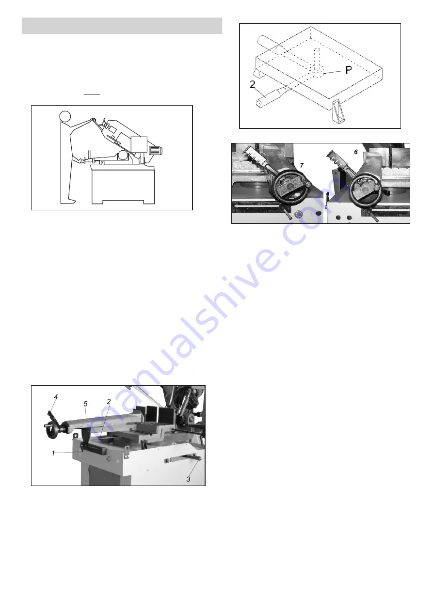
Only one operator is needed to use the machine, that 
must stand on the 

front

 of machine as shown in the 

picture.

Before starting each cutting operation, ensure that 
the part is firmly clamped in the vice and that  end is 
suitably supported.

Do not use blades of a different size from those stated 
in machine specifications.

If the blade gets stuck in the cut, release the running 
button immediately, switch off the machine, open the 
vice slowly, remove the part and check that the blade 
or its teeth are not broken. If they are broken, change 
the tool.

Clamping the work piece

Place work piece between the jaws.

Use the hand wheel to approach the vice jaw to the 
work piece, leaving 3-4mm of space. Lock down work 
piece by lowering the quick lock lever(

4

).

When the cutting cycle is finished, release vice by 
raising the quick lock lever (

4

). Upon releasing the 

quick lock lever (

4

), the vice jaw will open to the same 

distance that was set initially. This allows for rapid 
loading of same size material.

These figures below examples of suitable clamping of 
different section bars, bearing in mind the cutting 
capacities of the machine in order to achieve a good 
efficiency and blade durability.

Once


in


position,  move


the


lever(

2

)  to  the  right  to 

lock it into position.


If the lever (

2

)


is not between the 

vise/bed mounts and facing the user,


then the vise will 

not  be  able  to  lock.


If  the  vise  lever(

2

)  has  gone 

beyond or is obstructed by a vise/bed mount,


then use 

the following procedures.

Adjust


the


lever(

2

)


by  grasping  at  the  pivot  point(

P

)


and


lowering


it

which may assist in the adjustment

.

The  lever  can  now  be  freely  rotated  into  a  more 
convenient


position

Some  movement  of  the  vise 

Vice adjustment

jaw may be required.


Raise the lever (

2

)


then move to 

the right to lock.

The device does not require any particular adjustment

in case of excess play


of


the


sliding


guide

tighten 

Lock the track support(

1

) by turning handle clockwise.

slide screw more.

To  move  the  vise  in  either  direction,  the


vise


jaw


must


be


unlocked


at


two


points

.

Release


the


track  support  by  turning  the  handle(

1

counter-clockwise.

Release


the


vise


by


moving


the


lever(

2

) to the left.

The


vise (

5

) may now be moved to right position (

7

) or 

left position (

6

)by pushing it with one hand on the vise 

and the other hand on the track handle(

1

).

Fig 3

8

Fig 4

Fig 5

Fig 6

Summary of Contents for LM-270

Page 1: ...Manual Metal Cutting Band Saw Model LM 270 For your safety please read this manual before operation carefully...

Page 2: ...ty Instructions For The Adjusting 11 Metal cutting Bandsaw 2 Blade tension adjusting 11 Site Considerations 3 Adjusting the blade guide 11 Getting to Know your Metal Cutting Blade guide block 11 BandS...

Page 3: ...nsioned and is 2 REMOVE ADJUSTING KEYS AND WRENCHES Form habit of tracking on the center of the wheels checking to see that keys and adjusting wrenches are removed from tool before turning on 3 Always...

Page 4: ...ency continuously 0 98 1 02 short time The mains connection must have maximum16A fuse Electrical supply which has protection devices of under voltage over voltage over current as well as a residual cu...

Page 5: ...ight and the Feed Rate valve C Vise quick lock lever K Main motor D Jaw vise L Sling plate E Hydraulic cylinder M Coolant and chip tray F Saw arm N Bar stop work stop G Blade tension adjusting hand wh...

Page 6: ...Q Gear box R Fork Auto manual changing S Saw arm return spring T Hydraulic flow control valve W X Hydraulic flow regulation valve Stroke lower position limit switch Q R T W X 5...

Page 7: ...mm allen wrench 5 10 13 duo open wrench 17 19 duo open wrench Machine stand parts Right part Left part Bottom plate Door frame w door Shelf V H 16 Hex head screw M8x16 20 Washer 8mm 4 Hex nut M8 5 He...

Page 8: ...head onto base and fasten the If the machine is to be out of use for a long period it is machine head by 6 Hex head screw M10x20 and washer advisable to proceed as follows 10mm Detach the plug from th...

Page 9: ...g of same size material These figures below examples of suitable clamping of different section bars bearing in mind the cutting capacities of the machine in order to achieve a good efficiency and blad...

Page 10: ...speed and O is neutral Turn main connect switch QS fig8 to the ON position Check that the indicator light HL1 is on Load work piece and clamp it properly Press start reset button SB2 to start machine...

Page 11: ...push button K or SB1 to immediately stop all machine functions Lift the spring knob S to release the pin from its slot This will free the fork handle C Move the handle to the manual position C1 fig10...

Page 12: ...e the seat of the flywheels Assemble the blade guard and fasten it with relative knobs Check the safety microswitch is activated othewise when electric connection will be restored the machine will not...

Page 13: ...ge Turning the set screw counter clockwise will tilt flywheel so that the blade will ride away from the flange After the adjustment is finished fasten the hex screw in this order Q3 Q2 Q1 Checking the...

Page 14: ...he gear motor pump Special maintenance must be conducted by skilled and accident protection guarding personal We Advise contacting your nearest dealer and or importer Also the reset of protective and...

Page 15: ...hesis Choose the speed closest to the number tooth pitch blades and for standard raker type bi metal shown in the chart blades HSS blades However for exact specifications of bandsaw blades contact the...

Page 16: ...for the cutting of solid bars at maximum machine capacity Available Many conditions can lead to breakage Blade breakage is in pitches 3 4 4 6 some cases unavoidable since it is the natural result of t...

Page 17: ...i Low Speed Control SA2 Mode Switch KM Contactor FR Thermal protector TC Transformer FU1 3 Fuse 8A FU4 Transformer Fuse 2A HL1 Power Light HL2 Run Light SB1 Emergency Stop Button SB2 ON Button SB3 But...

Page 18: ...ting and feed speed Choose a suitable blade See Chapter Material classification and blade selection Check for clogging of coolant drain holes on the blade guide blocks and that flow is plentiful in or...

Page 19: ...or have hardened area or inclusion inside the section due to productive agents used such as casting sand welding wastes etc Avoid cutting these materials or perform cutting with extreme care cleaning...

Page 20: ...nst the support due to deformed or poorly welded bands tapered causing cracks and swelling of the back contour Check level of liquid in the tank Increase the flow of lubricating refrigerant checking t...

Page 21: ...on percentage The support and guide flange of the band are so worn out that they cannot ensure the alignment of the blade causing faulty cutting blade rolling and drawing tracks can have become tapere...

Page 22: ...eplace it if damaged It must be exactly turned to the Rabbit or Turtle sign Reset the emergency switch by following the steps of operation procedure Check electrical efficiency if not replace it Check...

Page 23: ...0 2 62 Nut M12 1 15 Tank Cover 1 63 Locking Lever 1 16 Filter 1 63 1 Set Screw M10x16 1 17 Pump 1 64 Allen Screw M10x35 1 18 Allen Screw M6x25 2 64 1 Spring Washer 10 1 18 1 Washer 6 2 65 Shaft Nut 1...

Page 24: ...0x50 1 151 Reduction Unit 1 95 2 Nut M10 1 151 1 Vent Screw 1 96 Handle M10x35 1 152 Key 8x7x30 1 97 Scale 1 153 Hex Cap Bolt M8x25 4 98 Rivet 3 153 1 Spring Washer 8 4 99 Chip Gutter 1 154 Motor 1 10...

Page 25: ...ixed Teeth 2 220 Nut M4 2 269 Adjustable Teeth 2 222 Handle 2 270 Allen Screw M5x8 2 223 Handle Wheel 1 271 Blade Guard 1 223 1 Thrust Bearing 51103 1 272 Guide Bracket 1 223 2 Blade Tension Gauge 1 2...

Page 26: ...1 307 1 Bushing 1 289 3 Hollow Pin 6x35 1 308 Shaft 1 291 Trigger Switch 1 309 Arm 1 292 Pipe 1 310 C Ring 12 3 292 1 Nut M16 1 311 Allen Screw M10x25 1 293 Nut M12 2 312 Spring Washer 10 1 294 Spring...

Page 27: ...26 24 4 A 330...

Page 28: ...27 68 328 329 66A...

Page 29: ...28 209A 325 326 327 211 212 213...

Page 30: ...29...

Reviews: