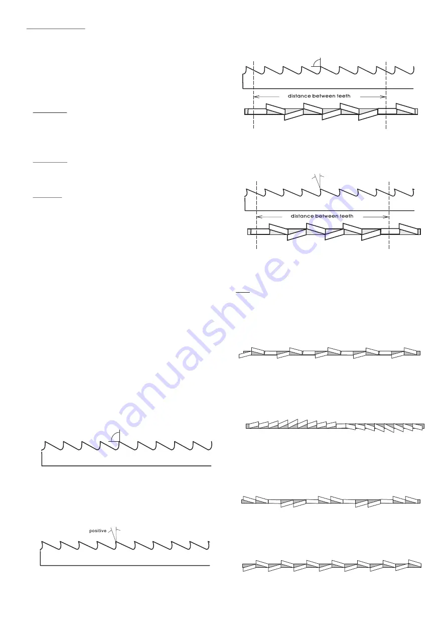
Aura LM-270 Manual Download Page 16

15

Blade


Structure

COMBO TOOTH

Pitch varies between teeth and consequently varying teeth 
size and varying gullet depths. Pitch varies between teeth, 

Bi-metal blade are the most commonly used. They consist of 

which ensures a smoother, quieter cut and longer blade life 

silicon-steel blade backing by a laser welded high speed steel 

owing to the lack of vibration.

(HSS) cutting edge. The type of stock are classified in M2, M42, 
M51 and differ from each other because their major hardness 
due to increasing percentage of Cobalt (Cc) and molybdenum 
(Mo) contained in metal alloy.

There


are


several


key


factors


to


consider


in choosing


a


blade

:

Tooth


Pitch---The


number


of


teeth


per


inch 

(

TPI

on


the


blade

also


known


as


tooth pitch

Select


a


pitch


which


will


assure


that at


least


three


teeth


are


contacting


the workpiece


while


cutting

This


helps


to


Another advantage offered in the use of this type of blade in 

distribute the


cutting


forces


and


avoids


tooth 

the fact that with an only blade it is possible to cut a wide 

breakage

.

range of different material in size and type.

Tooth


Form---There


are


four


common


forms of


teeth


on


the


COMBO TOOTH

blade

buttress

claw

-

tooth

precision


and


tungsten


O

O

9 -10  positive rake 

carbide

Precision


is the


most


common


and


is


the


type


supplied with


this


saw

Tooth


Set---Set


is


the


degree


to


which


the teeth


are


bent


away


from


the


blade

Typical tooth


set


styles


are


raker

wave


and


straight set

Always


select


and


use


good

-

quality


saw


blades and


choose


the


right


blade


for


the


job

Discuss your


cutting


requirements


with


your


saw


blade dealer


to


make


sure


you


are


getting


the


type


of blade


which


best


suits


your


need

Poor


quality blades


and


improper


use


are


often


the


cause


This type of blade is the most suitable for the cutting of 

of premature


blade


failure

.

section bars and large and thick pipes as well as for the 
cutting of solid bars at maximum machine capacity. Available 

Many


conditions


can


lead


to


breakage

Blade breakage


is

in


pitches: 3-4/4-6.

some


cases

unavoidable

since


it is


the


natural


result


of


the


peculiar


stresses


that bandsaw


blades


are


subjected


to

Sets

Blade


breakage is


also


due


to


avoidable


causes

Saw teeth bent out the plane of saw body, resulting in a wide 

Avoidable breakage


is


most


often


the


result


of


poor


care

cut in the work-piece.

or


judgement


on


the


part


of


the


operator


when  mounting


or


adjusting


the


blade


or


support


guides

The


most


common


Regular or Raker Set

causes


of


blade


breakage


are

:

Cutting teeth right and left, alternated by a straight 
tooth.

(1) faulty


alignment


and


adjustment


of


the


guides

;

(2) insufficient


number


of


teeth


contacting


the


cut

;

(3) feeding


too


fast

(4) tooth


dullness


or


absence of


sufficient


set

Of great use for materials with dimensions superior to 5mm. 

(5) excessive


tension

Used for cutting of steel, castings and hard nonferrous 

(6) using a


blade


with


a


lumpy


or


improperly


finished


materials.

weld

;

and


(7) continuously


running


the


bandsaw


when not


in


use

.

Wavy Set

REGULAR TOOTH

Set in smooth waves.

O

0  rake and constant pitch

This set is associated with very fine teeth and it is mainly 
used for cutting of pipes and thin section bars (from 1-3mm).

Most common form for transversal or inclined of solid small and 

Alternate Set (in groups)

average cross-sections or pipes, in laminated mild steel and 

Groups of cutting teeth right and left, alternated by a 

gray iron or general metal.

straight tooth.


POSITIVE RAKE TOOTH

O

O

9 -10  positive rake and constant pitch

This set is associated with very fine teeth and it is used for 
extremely thin materials (less than 1mm).

Alternate Set( individual teeth)

Cutting teeth right and left.

Particular use for crosswise or inclined cuts in solid sections or 
large pipes, but above all harder materials (highly alloyed and 

This set is used for the cutting of nonferrous soft materials, 

stainless steels, special bronze and forge pig iron).

plastics and wood.

Summary of Contents for LM-270

Page 1: ...Manual Metal Cutting Band Saw Model LM 270 For your safety please read this manual before operation carefully...

Page 2: ...ty Instructions For The Adjusting 11 Metal cutting Bandsaw 2 Blade tension adjusting 11 Site Considerations 3 Adjusting the blade guide 11 Getting to Know your Metal Cutting Blade guide block 11 BandS...

Page 3: ...nsioned and is 2 REMOVE ADJUSTING KEYS AND WRENCHES Form habit of tracking on the center of the wheels checking to see that keys and adjusting wrenches are removed from tool before turning on 3 Always...

Page 4: ...ency continuously 0 98 1 02 short time The mains connection must have maximum16A fuse Electrical supply which has protection devices of under voltage over voltage over current as well as a residual cu...

Page 5: ...ight and the Feed Rate valve C Vise quick lock lever K Main motor D Jaw vise L Sling plate E Hydraulic cylinder M Coolant and chip tray F Saw arm N Bar stop work stop G Blade tension adjusting hand wh...

Page 6: ...Q Gear box R Fork Auto manual changing S Saw arm return spring T Hydraulic flow control valve W X Hydraulic flow regulation valve Stroke lower position limit switch Q R T W X 5...

Page 7: ...mm allen wrench 5 10 13 duo open wrench 17 19 duo open wrench Machine stand parts Right part Left part Bottom plate Door frame w door Shelf V H 16 Hex head screw M8x16 20 Washer 8mm 4 Hex nut M8 5 He...

Page 8: ...head onto base and fasten the If the machine is to be out of use for a long period it is machine head by 6 Hex head screw M10x20 and washer advisable to proceed as follows 10mm Detach the plug from th...

Page 9: ...g of same size material These figures below examples of suitable clamping of different section bars bearing in mind the cutting capacities of the machine in order to achieve a good efficiency and blad...

Page 10: ...speed and O is neutral Turn main connect switch QS fig8 to the ON position Check that the indicator light HL1 is on Load work piece and clamp it properly Press start reset button SB2 to start machine...

Page 11: ...push button K or SB1 to immediately stop all machine functions Lift the spring knob S to release the pin from its slot This will free the fork handle C Move the handle to the manual position C1 fig10...

Page 12: ...e the seat of the flywheels Assemble the blade guard and fasten it with relative knobs Check the safety microswitch is activated othewise when electric connection will be restored the machine will not...

Page 13: ...ge Turning the set screw counter clockwise will tilt flywheel so that the blade will ride away from the flange After the adjustment is finished fasten the hex screw in this order Q3 Q2 Q1 Checking the...

Page 14: ...he gear motor pump Special maintenance must be conducted by skilled and accident protection guarding personal We Advise contacting your nearest dealer and or importer Also the reset of protective and...

Page 15: ...hesis Choose the speed closest to the number tooth pitch blades and for standard raker type bi metal shown in the chart blades HSS blades However for exact specifications of bandsaw blades contact the...

Page 16: ...for the cutting of solid bars at maximum machine capacity Available Many conditions can lead to breakage Blade breakage is in pitches 3 4 4 6 some cases unavoidable since it is the natural result of t...

Page 17: ...i Low Speed Control SA2 Mode Switch KM Contactor FR Thermal protector TC Transformer FU1 3 Fuse 8A FU4 Transformer Fuse 2A HL1 Power Light HL2 Run Light SB1 Emergency Stop Button SB2 ON Button SB3 But...

Page 18: ...ting and feed speed Choose a suitable blade See Chapter Material classification and blade selection Check for clogging of coolant drain holes on the blade guide blocks and that flow is plentiful in or...

Page 19: ...or have hardened area or inclusion inside the section due to productive agents used such as casting sand welding wastes etc Avoid cutting these materials or perform cutting with extreme care cleaning...

Page 20: ...nst the support due to deformed or poorly welded bands tapered causing cracks and swelling of the back contour Check level of liquid in the tank Increase the flow of lubricating refrigerant checking t...

Page 21: ...on percentage The support and guide flange of the band are so worn out that they cannot ensure the alignment of the blade causing faulty cutting blade rolling and drawing tracks can have become tapere...

Page 22: ...eplace it if damaged It must be exactly turned to the Rabbit or Turtle sign Reset the emergency switch by following the steps of operation procedure Check electrical efficiency if not replace it Check...

Page 23: ...0 2 62 Nut M12 1 15 Tank Cover 1 63 Locking Lever 1 16 Filter 1 63 1 Set Screw M10x16 1 17 Pump 1 64 Allen Screw M10x35 1 18 Allen Screw M6x25 2 64 1 Spring Washer 10 1 18 1 Washer 6 2 65 Shaft Nut 1...

Page 24: ...0x50 1 151 Reduction Unit 1 95 2 Nut M10 1 151 1 Vent Screw 1 96 Handle M10x35 1 152 Key 8x7x30 1 97 Scale 1 153 Hex Cap Bolt M8x25 4 98 Rivet 3 153 1 Spring Washer 8 4 99 Chip Gutter 1 154 Motor 1 10...

Page 25: ...ixed Teeth 2 220 Nut M4 2 269 Adjustable Teeth 2 222 Handle 2 270 Allen Screw M5x8 2 223 Handle Wheel 1 271 Blade Guard 1 223 1 Thrust Bearing 51103 1 272 Guide Bracket 1 223 2 Blade Tension Gauge 1 2...

Page 26: ...1 307 1 Bushing 1 289 3 Hollow Pin 6x35 1 308 Shaft 1 291 Trigger Switch 1 309 Arm 1 292 Pipe 1 310 C Ring 12 3 292 1 Nut M16 1 311 Allen Screw M10x25 1 293 Nut M12 2 312 Spring Washer 10 1 294 Spring...

Page 27: ...26 24 4 A 330...

Page 28: ...27 68 328 329 66A...

Page 29: ...28 209A 325 326 327 211 212 213...

Page 30: ...29...

Reviews: