Hardware Installation Manual
52
Document #: LTRT-40881
Mediant 1000B MSBR
For example, if the device requires one TRUNKS module and two FXS modules, then
you must insert the TRUNKS module in Slot 1 and the two FXS modules in slots 2 and
3 respectively. If at a later stage, you wish to add a BRI module (for example), then
you must replace the FXS module in Slot 2 with the new BRI module, and then re-
insert this replaced FXS module in Slot 4.
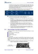
The figure below displays an example illustration of correct module slot assignment:
Figure
6-2: Recommended Priority Module Slot Assignment (Example)
The MPM module provides IP media channels for applications such as
announcements, conferencing, SBC, and IP-to-IP call routing:
•
When no other modules are used, up to three MPM modules can be housed in
the device.
•
For conferencing, one MPM module must be housed in Slot 6, providing 20 media
channels. For additional media channels, you can add MPM modules to slots 4
(40 channels) and 5 (40 channels) as well, thereby providing a total of 100 media
channels for conferencing.
•
For applications other than conferencing (e.g., SBC, IP-to-IP routing, and
announcements), the MPM modules can be housed in slots 3, 4, and 5. Each
module provides 40 channels; thereby, providing a total of 120 channels (60 for
IP-to-IP call sessions).
•
The device can acquire additional media channel resources (for SBC, IP-to-IP
routing, and conferencing) from the TRUNKS modules. For a description of this
configuration, refer to the device's
User's Manual
.
6.1.2
Removing Kapton Tape before Installing Modules
The following modules are supplied with Kapton tape covering their gold fingers (i.e., edge
of the module):
FXS, FXO, BRI, and TRUNKS (PRI)
CMX and CRMX
HDMX (OSN3 hard drive)
Fan
Power Supply
The Kapton tape is used to protect the module's BUS line. Before installing a new module,
you must remove this Kapton tape. If not removed, the module may not be functional,
chassis operation may be compromised and irreversible damage may be caused to the
chassis.
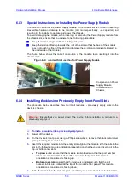
The figure below shows an example of a module with the Kapton tape over the gold finger:
Figure
6-3: Kapton Tape Covering Module's Gold Finger
Summary of Contents for Mediant 1000B
Page 1: ...Hardware Installation Manual Mediant 1000B MSBR Multi Service Business Router SIP Protocol ...
Page 2: ......
Page 12: ...Hardware Installation Manual 12 Document LTRT 40881 Mediant 1000B MSBR Reader s Notes ...
Page 14: ...Hardware Installation Manual 14 Document LTRT 40881 Mediant 1000B MSBR Reader s Notes ...
Page 34: ...Hardware Installation Manual 34 Document LTRT 40881 Mediant 1000B MSBR Reader s Notes ...
Page 70: ...Hardware Installation Manual www audiocodes com ...


