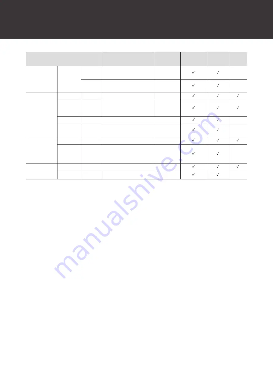
Audio Technica ATND1061DAN User Manual Download Page 73

Function List

72

Item

Setting values

Default

Setting

Presets

Included

Resumed

Web

Remote

Band#4 Q

value

0.3 to 60

0.75

-

Band#4

Filter type

LPF, HSH, PEQ

PEQ

-

AEC

AEC

On, Off

Off

AEC

Reference

Analog Input, Digital Input

Analog Input

NLP

On, Off

Off

-

NLP

Sensitivity

Low, Mid, High

Mid

-

NC

NC

On, Off

Off

NC

Attenuation

Level

0 to 20

6

-

AGC

AGC

On, Off

Off

Target Level

-10 to 10

0

-

[1] Capable of being set individually to Coverage and Priority 1 to Priority 5.

[2] Capable of being set individually to Coverage, Priority 1 to Priority 5, and Analog Input.

Summary of Contents for ATND1061DAN

Page 1: ...ATND1061DAN Beamforming Array Microphone User Manual Main Unit Edition English...

Page 2: ...nstallation 13 Surface mounting 13 Flush mounting 18 Grid ceiling installation 24 Surface mounting 24 Flush mounting 30 Installation with VESA mount 38 Removing the microphone 39 Surface mounting 39 F...

Page 3: ...unch from Locate 54 Launch by directly specifying the IP address 54 Basic operations on Setting Maintenance screen 54 General System Settings 56 Device Name 56 LED Settings 56 Dimmer Settings 56 Netwo...

Page 4: ...ions 76 ATND1061DAN 76 Surface mount adapter 77 Flush mount adapter 78 Flush mount cover 79 Tile bridge A 79 Tile bridge B 80 Tile bridge C 80 Assembly diagram of tile bridge for grid ceiling 81 Speci...

Page 5: ...duct in a location where it is exposed to direct sunlight near heating devices or in places with high temperatures high humidity or high concentrations of dust to avoid electric shock fire malfunction...

Page 6: ...o communications However there is no guarantee that interference will not occur in a particular installation If this equipment does cause harmful interference to radio or television reception which ca...

Page 7: ...damping measures are recommended Be sure to use only the included accessories for installation Do not use the included accessories for any purpose other than for use with this product Do not install...

Page 8: ...7 Maintenance When dirty or dusty wipe clean using a dry soft cloth Do not use benzine paint thinners or electrical contact cleaners Doing so may cause deformation or malfunction...

Page 9: ...8 Package contents 1 2 3 4 5 6 7 8 9 10 11 12 13 14 17 16 15 18 19 1 Microphone 2 IR remote controller Includes a lithium coin battery...

Page 10: ...sh mount adapter 6 Flush mount cover 7 Screw M4 10 mm 12 8 Hole cover 9 Nut 4 10 Snap bushing 2 11 Tile bridge A 2 12 Tile bridge B 2 13 Tile bridge C 4 14 Seismic cable 15 Zip tie 16 Safety belt 17 E...

Page 11: ...g with a VESA mount 7 Network A B ports Dante network ports Used for connecting the LAN cable CAT5e or higher Make sure to use conductor with a diameter of 24AWG or larger and a shield Connect to the...

Page 12: ...ts in green 1 Normal unmuted Lights in red 1 Muted Lights in cyan 1 Power Save Mode Flashes in red 1 second intervals Connecting to the network Flashes in red 2 second intervals Error 1 The colors of...

Page 13: ...presets Presets can be changed using the IR remote controller Settings in presets 1 to 4 will be recalled For details on presets see Presets p 65 1 Press the preset mode button The indicator lamp on t...

Page 14: ...installation Surface mounting Completed installation Parts required for installation 1 2 3 4 7 5 6 1 Surface mount adapter 2 Screw M4 50 mm 4 3 Tile bridge A 2 4 Tile bridge B 2 5 Seismic cable 6 Zip...

Page 15: ...B to the inside of the ceiling Align the screw holes of tile bridges A and B with the holes drilled into the ceiling to attach Securely attach tile bridges A and B to the ceiling frame so that a suffi...

Page 16: ...orientation 4 Run the cables inside the ceiling 5 Attach the seismic cable to the ceiling frame Securely attach the seismic cable to a strong point on the ceiling frame Slide the unlock pins to releas...

Page 17: ...he cables and the seismic cable through the hole in the surface mount adapter 7 Attach the seismic cable to the microphone using the screw for seismic cable 1 1 Screw for seismic cable 8 Connect the w...

Page 18: ...Installation 17 1 2 1 Zip tie 2 Tab on surface mount adapter 10 Tighten the zip tie to secure...

Page 19: ...Installation 18 Flush mounting Completed installation Parts required for installation 1 2 3 4 5 6 7 8 9 10 13 12 11 1 Surface mount adapter...

Page 20: ...before choosing an installation location Max ceiling thickness for installation 25 mm 290 mm 290 mm 2 Attach tile bridges A and tile bridges B to the inside of the ceiling using the screws M4 10 mm Ad...

Page 21: ...e flush mount adapter using the screws M4 10 mm Align the arrows on both the flush mount adapter and the stamping on surface mount adapter when attaching 4 Attach the hole cover with the nuts If using...

Page 22: ...le When wiring a large number of cables attach both snap bushings without using the hole cover 6 Run the cables inside the ceiling 7 Attach the seismic cable to the ceiling frame Securely attach the s...

Page 23: ...new one 8 Pass the cable and the seismic cable through the snap bushing hole in the flush mount adapter insert the flush mount adapter into the square hole cut into the ceiling and secure with screws...

Page 24: ...pter Make sure the tab on the surface mount adapter is securely hooked on the microphone before pushing up the other side of the microphone to attach it 1 1 Tab on surface mount adapter 12 Attach the...

Page 25: ...Attach the flush mount cover by inserting it into the flush mount adapter Avoid bending or twisting the safety belt when attaching the flush mount cover Grid ceiling installation Surface mounting Comp...

Page 26: ...M4 10 mm 4 6 Seismic cable 7 Zip tie 8 Installation template 1 Remove the ceiling tile where the microphone will be installed 2 Drill holes in the ceiling tile for attaching the microphone Use the enc...

Page 27: ...ridges C loosely to tile bridges A using the screws M4 10 mm Align the screw holes of tile bridges A with the holes drilled into the ceiling tile to attach 4 Attach the surface mount adapter using the...

Page 28: ...ck pins Attach the seismic cable so that there is as little slack as possible Using the seismic cable with a large amount of slack could increase the impact exerted were the microphone to be dropped a...

Page 29: ...ng frame so that a sufficient load can be supported If the placement of the ceiling frame makes it difficult to ensure a secure installation use nuts and bolts to attach tile bridges A securely to the...

Page 30: ...s 11 Pass the zip tie through the microphone and the surface mount adapter to attach the microphone to the surface mount adapter Make sure the tab on the surface mount adapter is securely hooked on th...

Page 31: ...Installation 30 Flush mounting Completed installation...

Page 32: ...ion 1 2 3 4 5 6 7 8 9 10 13 12 11 1 Surface mount adapter 2 Flush mount adapter 3 Flush mount cover 4 Screw M4 10 mm 12 5 Hole cover 6 Nut 4 7 Snap bushing 2 8 Tile bridge A 2 9 Tile bridge B 2 10 Til...

Page 33: ...ole according to the specified dimensions Align the mounting holes with the center of the ceiling tile Max ceiling tile thickness for installation 25 mm 290 mm 290 mm 3 Attach tile bridges A and tile...

Page 34: ...e flush mount adapter using the screws M4 10 mm Align the arrows on both the flush mount adapter and the stamping on surface mount adapter when attaching 5 Attach the hole cover with the nuts If using...

Page 35: ...cover 7 Insert the flush mount adapter into the square hole cut into the ceiling tile and secure with screws to attach the flush mount adapter The stamping on the surface mount adapter indicates the...

Page 36: ...is as little slack as possible Using the seismic cable with a large amount of slack could increase the impact exerted were the microphone to be dropped and may result in an accident injury or damage t...

Page 37: ...ing frame so that a sufficient load can be supported If the placement of the ceiling frame makes it difficult to ensure a secure installation use nuts and bolts to attach tile bridges A securely to th...

Page 38: ...icrophone to the surface mount adapter Make sure the tab on the surface mount adapter is securely hooked on the microphone before pushing up the other side of the microphone to attach it 1 1 Tab on su...

Page 39: ...tallation is possible using a commercially available VESA mount VESA standard dimensions 75 mm pitch Mounting screw hole M4 8 mm depth Do not use screws with a length that exceeds the sum of the mount...

Page 40: ...on the structure of the VESA mount 1 2 75 mm 75 mm 1 Screw holes for VESA mount 2 Screw for seismic cable Removing the microphone Surface mounting 1 Cut away the zip tie used to secure the microphone...

Page 41: ...o the flush mount adapter Insert a flathead screwdriver as far into the recess of the flush mount cover as possible and lower the flush mount cover downward while pushing in the tab Removal can be fac...

Page 42: ...Installation 41...

Page 43: ...procedure System connection examples ATND1061DAN single cable mode Dante DSP Far end source ATND1061DAN Power amplifier Router Computer Internet Video conference system Speaker PoE switching hub A ATN...

Page 44: ...dure 43 ATND1061DAN split mode Dante DSP Far end source ATND1061DAN Power amplifier Router Computer Internet Video conference system Speaker Switching hub PoE switching hub A B ATND1061DAN Back Dante...

Page 45: ...e ATND1061DAN Power amplifier Router Computer Internet Video conference system Speaker PoE switching hub A ATND1061DAN A ATND1061DAN A ATND1061DAN A ATND1061DAN Back For details on auto mix settings w...

Page 46: ...ystem Speaker PoE switching hub PoE IP Control ATND1061DAN Back INPUT OUTPUT 1 2 1 OUTPUT Connection to analog input for video conference system far end transmission 2 INPUT Connection to analog outpu...

Page 47: ...head screwdriver 3 Check the pin assignments and connect each cable B A C Terminal Pin assignments INPUT A Hot B Cold C G Ground OUTPUT A Hot B Cold C G Ground GPI A 1 GPI1 B 2 GPI2 C G Ground 4 Loose...

Page 48: ...selected under GPI Setting in Digital Microphone Manager The function assigned to the GPI port is executed by closing the GPI port and ground port Close them for at least 0 5 seconds Item Description...

Page 49: ...in green Auto Flashes in orange Static Network reset The following network settings will be reset IP Control Web Remote Port Settings Allow Discovery IP Control Settings 1 Press and hold the reset bu...

Page 50: ...nge 2 Press the reset button while the indicator lamp is switching between being lit in green and orange If there is no operation within 5 seconds of the indicator lamp switching between being lit in...

Page 51: ...lly installed It also enables users to perform real time editing and display speaker positions in an online environment a useful feature for on site adjustments of advanced settings Digital Microphone...

Page 52: ...output 5 or auto mix signal output selection possible AEC Ref Out Outputs AEC reference signals used with auto mix Sum Out Used for auto mix when connecting multiple units Outputs control signals to...

Page 53: ...Recommended environment OS for running Web Remote and Locate Microsoft Windows 8 1 or later macOS Mojave or later Android OS 8 0 or later iOS 12 or later Recommended web browsers for Web Remote Googl...

Page 54: ...w audio technica com for the country or region where used If using iOS or Android Download from the App Store or Google Play Proceed to step 4 once downloaded 2 Double click the downloaded setup exe T...

Page 55: ...ess of the microphone Web Remote can be launched by directly specifying the IP address 1 Launch the web browser of the control device 2 Enter the IP address of the microphone for which Web Remote will...

Page 56: ...for the setting and make a selection from the pull down menu 4 For settings requiring use of a switch click the switch Switching between ON blue and OFF no color will occur with each click 5 For sett...

Page 57: ...Color Set indicator lamp colors for microphones when in power save mode Dimmer Settings Item Description Enabled Turn microphone indicator lamps ON or OFF When set to ON blue the indicator lamp lights...

Page 58: ...fig Mode is set to Static IP Control Web Remote Port Settings Item Description IP Config Mode Set the configuration mode for the IP address When Auto is selected IP addresses are automatically assigne...

Page 59: ...Notification 1 Set whether to receive camera detection notifications from microphones during IP control Setting to ON blue will result in notifications being received Multicast Address 1 Set the addre...

Page 60: ...ar and the microphone will automatically reboot Reset All Settings to Default All microphone settings will be reset to factory default However the firmware version will remain the same 1 Click Reset 2...

Page 61: ...this function Level Set the level of audio input Mute Set whether to mute or unmute Setting to ON blue will mute audio Gain Share Set whether to enable auto mix Setting to ON blue will enable this fun...

Page 62: ...control Setting to ON blue will enable this function Level Set the level of audio output Analog Output Item Description Unity Set the unity level Level Set the level of audio output Dante Tx 6 Signal...

Page 63: ...o a file 1 Click the button s of the preset s to be exported to a file 2 Click Export 3 Export after specifying the export location and file name Importing presets Import exported preset files 1 Click...

Page 64: ...Web Remote 63 2 Click Browse 3 Select and open preset files from the file selection screen 4 Click Import The preset s will be imported...

Page 65: ...ll download log files registered to internal memory 1 This is possible when Enabled is set to ON Syslog is a standard for forwarding log messages over IP networks It is used to manage computer systems...

Page 66: ...is present 5 Presets Displays the preset selection and name of the imported preset s Displaying descriptions of errors If a triangle mark is displayed in the icon click on the icon to display a descr...

Page 67: ...ck the slot where the preset is to be saved 4 Enter a name 5 Click Save It may take several minutes to save presets Settings for the microphone are saved in the preset For information on importing and...

Page 68: ...Web Remote 67 2 Click Recall Preset in the pull down menu 3 Click the preset to be recalled The preset is reflected in the microphone settings...

Page 69: ...Save Mode Dante Network Configuration Mode Single Cable Split Single Cable Latency 0 25 msec 0 5 msec 1 msec 2 msec 5 msec 0 5 msec Dante Audio Port Settings IP Config Mode Auto Static Auto IP Addres...

Page 70: ...uto Mix LED Settings Unmute Color Black No light Red Orange Yellow Pink Purple Blue Aqua Green Cyan White Green Mute Color Black No light Red Orange Yellow Pink Purple Blue Aqua Green Cyan White Red P...

Page 71: ...nk Blue Gray Dark Gray CH1 Green CH2 Yellow CH3 Brown CH4 Red CH5 Pink CH6 Blue Level 120 0 dB to 10 0 dB 0 0 dB CH Mute On Off Off Analog Input Mode Select Mic Line Line Input Gain Mode When Mic 0 25...

Page 72: ...rm 3 Warm 4 Warm 5 Warm 6 Neutral Bright 6 Bright 5 Bright 4 Bright 3 Bright 2 Bright 1 Bright Neutral Expert Mode Band 1 Frequency 20 Hz to 20000 Hz 25 Band 1 Gain 18 dB to 18 dB 0 Band 1 Q value 0 3...

Page 73: ...ff Off AEC Reference Analog Input Digital Input Analog Input NLP On Off Off NLP Sensitivity Low Mid High Mid NC NC On Off Off NC Attenuation Level 0 to 20 6 AGC AGC On Off Off Target Level 10 to 10 0...

Page 74: ...Review firewall settings Check Digital Microphone Manager and Web Remote to see whether Allow Discovery Enabled is set to ON Microphone is not recognized by Dante Controller Check Digital Microphone...

Page 75: ...is set to ON AEC does not function Check Digital Microphone Manager and Web Remote to see whether settings for AEC AEC Reference are correct Check whether far end audio is routed to AEC Ref In of the...

Page 76: ...Troubleshooting 75 No incoming IP control notifications Check Digital Microphone Manager and Web Remote to see whether IP Control Settings Notification is set to ON...

Page 77: ...76 Dimensions ATND1061DAN 227 5 30 227 5 Unit mm...

Page 78: ...Dimensions 77 Surface mount adapter 44 5 105 70 106 204 5 80 9 5 19 5 60 45 8 89 106 204 5 0 5 10 2 4 4 8 4 5 4 4 5 4 4 5 2 4 5 2 9 9 Unit mm...

Page 79: ...Dimensions 78 Flush mount adapter 307 34 5 39 307 283 105 283 70 38 1 Unit mm 2 2 2 4 M 4...

Page 80: ...Dimensions 79 Flush mount cover 315 315 12 6 5 Unit mm Tile bridge A Unit mm 30 8 553 4 M 4 10 5 10 5 5 5 5 50 596 25 15 106 106 106 40 63 8...

Page 81: ...Dimensions 80 Tile bridge B M 4 2 5 19 40 32 106 289 372 4 Unit mm Tile bridge C Unit mm 12 8 20 42 5 47 5 25 12 45 M 4...

Page 82: ...ly diagram of tile bridge for grid ceiling Unit mm 34 5 290 400 596 17 5 5 20 370 320 370 417 6 10 5 10 5 10 5 5 5 6 9 Center Adjust Max84 5 34 5 30 8 19 8 Adjust Max29 6 17 5 5 20 5 5 6 9 Center Adju...

Page 83: ...000 Hz Sensitivity 8 dBFS 1 kHz 94 dBSPL Dynamic range 89 dB A weighted Signal to noise ratio 61 5 dB A weighted Self noise 25 dBSPL A weighted Maximum input sound level 102 dBSPL Analog audio Freque...

Page 84: ...roblock 3pin Analog output Euroblock 3pin GPI Euroblock 3pin Phantom power Analog input 12 V Included accessories IR remote controller Surface mount adapter Screw M4 50 mm 4 Flush mount adapter Flush...

Page 85: ...r pattern 200 Hz 1 kHz 5 kHz 8 kHz SCALE IS 5 DECIBELS PER DIVISION LEGEND 240 180 210 270 300 330 0 150 120 90 30 60 Frequency response 20 10 dB 100 50 200 10k 5k 1k 500 2k 20k 0 50 cm LEGEND Frequen...

Page 86: ...ts abbreviated form as Windows Mac OS and Safari are trademarks of Apple Inc registered in the U S and other countries Android and Google Chrome are trademarks of Google LLC Firefox is a trademark of...

Page 87: ...s out Rx1 AEC Ref In Rx2 Sum In Gain Share BUS Level AEC AEC Ref Mute Auto Mix Assign ON OFF Beam 3 Beam 4 Beam 5 Beam 6 Auto Mix Meter Level CH1 NLP NC AGC AEC Ref Select Analog Input Tx2 CH 2 Tx4 CH...

Page 88: ...technica co jp Audio Technica Corporation 2 46 1 Nishi naruse Machida Tokyo 194 8666 Japan www audio technica com 2022 Audio Technica Corporation Global Support Contact www at globalsupport com 142700...

Reviews: