3
Connections and Controls
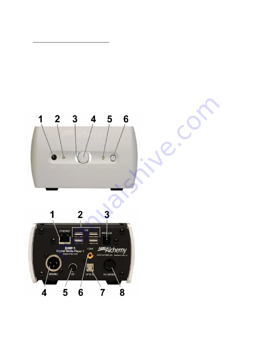
Front Panel
1. IR input for remote control
2. LED input indicator
3. LED power indicator
4. Power button
5. LED on/off (pause/mute) indicator
6. Mute button
Rear Panel
1. RJ-45 Ethernet jack
2. USB jacks
3. Standard AC power supply input
4. AES/EBU digital output
5. I
2
S digital output
6. Coaxial SPDIF digital output
7. Optical Toslink digital output
8. Optional PS-5 power supply input
Important Guidelines for Installation and Use
■
Do not place the power supply on a carpet. It can get warm during operation and some carpets can be damaged by di-
rect contact with warm surfaces. Place the power supply on a solid surface, such as a tabletop, shelf or rack shelf.
■
Do not connect the DMP-1's power supply until all audio connections have been made.
■
Place the DMP-1 where it will not be exposed to moisture or direct sunlight.
■
Install the DMP-1 and its power supply where they can get some ventilation. They don't produce a great deal of heat, but
using them in a sealed enclosure with no airflow could have long-term negative effects on the unit's circuitry.
■
Use a soft microfiber cloth to clean dust and fingerprints off of the DMP-1's surface. Stubborn fingerprints or dirt may be
removed by spraying a small amount of water or window cleaner onto the cloth, then using the moistened cloth to clean the
DMP-1. Do not spray any cleaner or other moisture directly onto the DMP-1.
■
You will get the best and most reliable performance from the DMP-1 by using high-quality digital audio cables. We rec-
ommend against using the "freebie" cables included with some components.


