background image

15

Chapter 3

Wiring up the system

NOTE

Make sure the power of the system is switched off, when any changes to the connections 
are being made.

RS485:

In case your system is using the RS485 bus protocol, avoid making any star structured 
constructions in your cabling. In installations where multiple ARU’s are connected in a bus 
structure it is important that the data bus is connected as a daisy chained structure and the 
last device terminates the bus on its characteristic impedance through placement of the bus 
termination jumper. All other devices connected in this bus structure should not have the bus 
termination jumpers on off position. 

The connection between the ARU’s (RS485) shall be made with twisted pair cabling (CAT5E 
or higher). The Ethernet connection shall also be established with CAT5E (or higher) cabling. 

Power supply (24 V DC):

The complete system can be powered using a single 24 V DC power supply. The voltage is 
distributed through the RS485 databus connection and other connected ARU’s will be fed 
accordingly when connected in daisy chained structure. If cable distances larger than 300 
meters will occur, the cable length will make the voltage drop below the required level and 
additional power supplies needs to get added locally.

Ethernet:

To establish a proper Ethernet connection, CAT5E (or higher) cabling needs to be used for 
connecting the ARU to your Ethernet network.

Relay connections:

Any kind of signals within the systems limitations can be switched and controlled through 
the ARU unit. Depending on the type of signal and the system regulations or restrictions, the 
signals needs to be connected using the appropriate cable and wiring standards. 

Contact inputs:

The contact inputs on the ARU20x are dry contact inputs which can be used for triggering 
relays by external devices or actuators. The contacts are triggered by connecting the particular 
terminal for the relay to ground. When triggering the triggering the ‘A’ contact, all contacts 
will switch simultaneously. 

Summary of Contents for ARU20 Series

Page 1: ...ARU20x User Manual www audac eu ...

Page 2: ...on date However updates on the specifications functionality or software may have occurred since publication To obtain the latest instruction manual or obtain additional product information please visit the product page on www audac eu For information about software version updates please visit www audac eu software ...

Page 3: ...onnections and connectors 9 Connection standards 9 Chapter 2 ARU20x Overview 10 Connection description 10 Contact description 11 Internal settings 12 Connections overview 14 Chapter 3 Wiring up the system 15 Chapter 4 Application examples 16 Chapter 5 User interface configuration 17 Login 17 Dashboard 18 Events 19 Settings 20 Chapter 6 IP basics 24 Chapter 7 Technical specifications 26 ...

Page 4: ...4 ...

Page 5: ...modular nature the ARU20x is perfectly suitable for small home or retail applications as well as big installations There is no limit to the amount of ARU s connected to one system The TCP IP functionality allows controlling the ARU20x over an existing ethernet network through an integrated HTML5 webserver achieving full control via any connected PC laptop or smart device An RS485 control port allo...

Page 6: ...AIN HIGH LEVELS OF DUST HEAT MOISTURE OR VIBRATION THIS UNIT IS DEVELOPED FOR INDOOR USE ONLY DO NOT USE IT OUTDOORS PLACE THE UNIT ON A STABLE BASE OR MOUNT IT IN A STABLE RACK ONLY USE ATTACHMENTS ACCESSORIES SPECIFIED BY THE MANUFACTURER UNPLUG THIS APPARATUS DURING LIGHTNING STORMS OR WHEN UNUSED FOR LONG PERIODS OF TIME EC DECLARATION OF CONFORMITY This product conforms to all the essential r...

Page 7: ...le harm to the environment or human health This product is developed and manufactured with high quality materials and components which can be recycled and or reused Please dispose this product at your local collection point or recycling centre for electrical and electronic waste This will make sure that it will be recycled on an environmentally friendly manner and will help to protect the environm...

Page 8: ...8 ...

Page 9: ... White Orange Not used Pin 2 Orange Not used Pin 3 White Green 24V DC Pin 4 Blue RS485 A Pin 5 White Blue RS485 B Pin 6 Green GND Pin 7 White Brown Paging audio Pin 8 Brown Paging audio Audio signal inputs and outputs must be connected with high quality audio cable and high quality connectors RS485 TCP IP The ARU20x has RS485 and TCP IP control ports which all accept the same commands The complete...

Page 10: ...r better cabling and 10 Mbit compatible network infrastructure RS485 The RS485 databus is connected using RJ45 connectors and allows integration of the ARU20x in any RS485 controlled system It allows integration with peripheral devices connected to your audio system or any other RS485 based network The ARU208 contains two RS485 connections allowing daisy chaining of multiple units The RS485 shall ...

Page 11: ...s connected to the RS485 databus the analogue line output signal from the paging console is available on this terminal The line output is a balanced audio signal This signal shall be fed to all the relay inputs which are meant for switching the paging audio signal to the outputs and the connection should be done by external wiring When connecting the analogue output signal to an external amplifier...

Page 12: ...ained through the RS485 bus the last ARU in the chain needs to have the bus termination jumper placed to terminate it on the correct characteristic impedance avoiding reflections and guaranteeing a reliable signal transmission The bus termination jumper JP1 is default configured as terminated meaning only one device connected to the ARU20x s RS485 databus Terminated default Not terminated Ground l...

Page 13: ...udio outputs Paging mode Relay condition Audio condition Power on output not activated 14 11 14 11 Music Power on output activated 12 11 12 11 Paging Power off 12 11 12 11 Paging In paging mode the power off condition is equal to the output active condition Normal mode At power on all relays will remain in idle state and they require a trigger for activation This configuration is recommended when ...

Page 14: ...n 2 Ethernet RJ45 connection 3 RS485 databus connection RJ45 with linkthrough for daisy chaining only ARU208 4 Contact trigger inputs 5 Relay contact outputs 6 Analogue audio line out connection balanced 7 Normal open NO relay contact inputs 8 Normal closed NC relay contact inputs ...

Page 15: ... DC power supply The voltage is distributed through the RS485 databus connection and other connected ARU s will be fed accordingly when connected in daisy chained structure If cable distances larger than 300 meters will occur the cable length will make the voltage drop below the required level and additional power supplies needs to get added locally Ethernet To establish a proper Ethernet connecti...

Page 16: ...l amplifiers for amplification of the signals for each particular zone In normal situation the music coming from the background music source will be heard in all zones the relays will be switched to background music In case of an announcement the ARU will switch to the signal from the paging microphone for the channels which were selected through the APM keypad and the announcement will be heard i...

Page 17: ...connected to an ethernet LAN network and accessed by its IP address The standard factory default IP address of the ARU20X is 192 168 0 197 make sure this address is within the IP range of the connected ethernet LAN network subnetmask 255 255 255 0 Start your default web browser and enter the IP address of the embedded web control interface in the address bar The factory default IP address is http ...

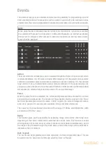
Page 18: ...om of the relay knobs buttons for selecting all All on or deselecting all All off are located allowing to switch all relays simultaneously The knobs will be indicated in a neutral color grey when the relays are in the idle state while they will turn blue when activated The text inside the relay knob is default shown as Relayx where x represents the number of the corresponding relay 1 up to 4 for A...

Page 19: ...rtain period defined in milliseconds and the radio button will activate the selected relays and will switch off non selected relays Pulse When the pulse function is selected the corresponding relays will be activated for a certain period defined in milliseconds The duration of the activation shall be entered in the Pulse text field Example given when the value 10000 is given the selected relays wi...

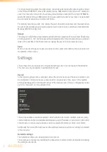
Page 20: ... made all events will be saved after clicking the save button on the bottom of the screen Settings The settings screen includes all configurable settings which can be made to the ARU20x This menu is only accessible in administrator mode Device In the device settings menu settings such as the device name and the device address can be configured The device name is only used for convenience of the us...

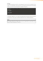
Page 21: ...ot IP address The IP address for the system can be configured in this window Adjustment of these settings is just done by manual changing the values of the text fields Network settings All other network settings such as subnet mask Gateway DNS 1 and DNS 2 can be configured in this window The default settings are configured in such way to suit most typical installations requirements In case of spec...

Page 22: ...imeserver is being used which always guarantees an accurate synchronization of the system according to GMT Depending of the time zone and or location the GMT offset settings have to be made accordingly In case your system is restricted from access to internet an internal time server on your LAN network should get assigned offering synchronization to the system The IP address of the internal time s...

Page 23: ...s and settings while the user level only has access to the dashboard functions To change the passwords click change shown besides the text fields and the new password can get entered Press enter to confirm and save the newly configured passwords SAVE Any changes made in the settings menu will only be saved after the save button on the bottom of the settings screen is pressed ...

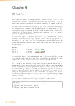
Page 24: ...ate with each other Example Device 1 IP address 192 168 000 001 Device 2 IP address 192 168 000 002 Device 3 IP address 192 168 001 003 In this example Device 1 can communicate with Device 2 but not with Device 3 because the first three numbers must be the same These first three parts are called the IP range so the devices must be in the same IP range to communicate with each other The IP range of...

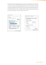
Page 25: ...Find the Ethernet properties settings screen the new IP address can be set in the Internet Protocol Version TCP IPv4 Your PC must have an IP address like 192 168 0 x x is a value between 2 254 the address must be unique Do not use 192 168 0 197 or any other IP address currently in use Once saved it is possible using any standard browser to access the web interface using the address 192 168 0 197 ...

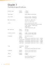
Page 26: ...ction standard RS485 CAT5E or better TIA EIA T568B Ethernet CAT5E or better TIA EIA T568B Connections RS485 RJ45 2x for ARU208 Ethernet RJ45 24 V DC Terminal block connector max 2 5 mm 14 AWG Contact inputs Terminal block connector max 1 0 mm 17 AWG Relay inputs Terminal block connector max 2 5 mm 14 AWG Relay outputs Terminal block connector max 2 5 mm 14 AWG Audio output Terminal block connector...

Page 27: ...27 Notes ...

Page 28: ...28 Notes ...

Reviews: