28
Chapter 5
Peripheral connections
In addition to the direct line and microphone inputs on the AMP523, additional wall
line and microphone inputs can be connected. It provides the possibility to connect
one additional Wall Line Input (WLI) and one additional Wall Microphone Input (WMI).
To control the standard functions like input selection and general volume control, an
additional MWX43/45 wall panel can be connected.
The additional units must be connected to the “RS485 + AUDIO” RJ45 input
connector. The data transfer between both audio input units and the control units is
done over a single CAT5 (or better) cable. The wiring should be straight, according to
the wire colour coding as shown in “Chapter 1: Pin connections and connectors” of
this user manual.
The signal coming from the Wall Microphone Input is combined with the direct
microphone input and priority settings also affect the Wall Microphone input signal.
Both inputs are mixed with each other and the volume for each channel can be set
separately by using the fader on the web-based user interface.
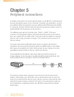
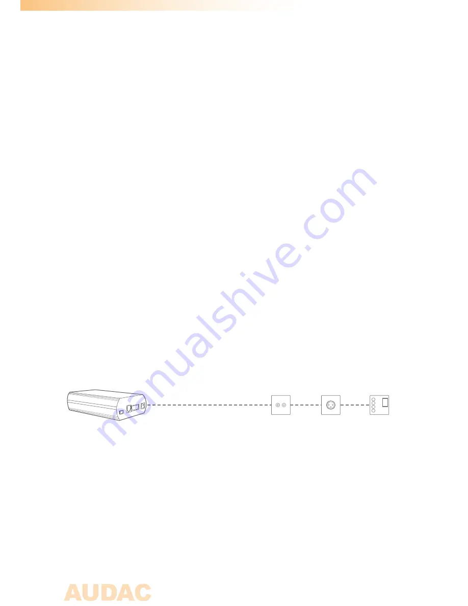
The wiring between the different units simply needs to be linked-through. An
example diagram of how the system including the additional wall audio inputs and
control panel should be connected is shown in the diagram below.
The maximum cable distance depends on the amount of connected units on the
databus. Cable lengths up to 300 meters can be achieved when only one input unit
needs to be connected. When two (or more) units are connected, the maximum cable
length for the entire databus is limited to 150 meters. The maximum bus length can
be increased when an additional junction box (ARJ03P) is placed with an external
power supply.
WLI
Prog.
Vol
+
-
+
-
WMI
MWX43/45
AMP523
Cat5
Summary of Contents for AMP523
Page 1: ...AMP523 RM523 User Manual www audac eu ...
Page 2: ...2 ...
Page 4: ...4 ...
Page 8: ...8 ...
Page 14: ...14 Block Diagram ...


