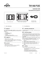


TH146-P-DE
400-280-004-C 11/29/06 3/9
NOTE
: In this mode, the short-cycle protection is disabled and
the interstage delay is reduced to 1 minute.
USER:
User mode. Gives access to configuration parameters 1 to 4
only.
n
Place the controller in Installer mode (INST) using the SW2
selector switch on the back of the console.
o
Press the
Mode
button for 3 seconds to access the configura-
tion menu (see page 4). The first menu item (parameter) is dis-
played.
p
To view another menu item, briefly press the
Mode
button.
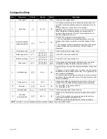
The following table shows the order in which the parameters
appear as well as a description of each parameter.
q
To modify a parameter, press either
button.
r
To exit the configuration menu, press .
s
Return the controller to User mode (USER) using the SW2
selector switch.
With automatic changeover, there’s no need to adjust the controller
at every change of season or weather condition. The controller
switches automatically between heating mode and cooling mode to
maintain the desired temperature.
Manual Mode
When the controller is in manual mode, the heating/cooling mode
changeover occurs as follows:
•
The controller switches to cooling mode when the indoor tem-
perature is higher than the setpoint by more than 1.5°C (2.5°F)
for 15 minutes.
•
The controller switches the heating mode when the indoor tem-
perature is lower than the setpoint by more than 1.5°C (2.5°F)
for 15 minutes.
Automatic Mode
When the controller is in automatic mode, it follows the programmed
schedule. Two temperature settings (heating setpoint and cooling
setpoint) are programmed for each period of the schedule. The
heating/cooling mode changeover occurs as follows:
•
When the controller is in heating mode, the indoor temperature
is maintained at the heating setpoint. However, if the tempera-
ture rises and remains above the cooling setpoint for 15 min-
utes, the controller will switch to cooling mode.
•
When the controller is in cooling mode, the indoor temperature
is maintained at the cooling setpoint. However, if the tempera-
ture drops and remains below the heating setpoint for 15 min-
utes, the controller will switch to heating mode.
Balance points are used to disable the heat pump operation or aux-
iliary heating below or above a certain temperature.
•
When the outdoor temperature is below the balance point low
(bP L), the heat pump is disabled and only auxiliary heating can
used (see page 4, item 5).
•
When the outdoor temperature is above the balance point high
(bP H), the auxiliary heat is disabled (see page 4, item 6) and
only the heat pump can be used.
NOTE
: Balance points will not work if the AC144-03 outdoor tem-
perature sensor is not connected to the controller.
The auxiliary heat is activated during defrost except under the fol-
lowing conditions:
•
When the outdoor temperature is above the defrost point (see
page 4, item 7).
NOTE
: This condition will not apply if the
AC144-03 outdoor temperature sensor is not connected to the
controller.
•
When the plenum temperature is above 40°C (104°F). The
auxiliary heat is re-activated when the plenum temperature
drops below 32°C (90°F).
NOTE
: This condition will not apply if
the AC146-410 plenum sensor is not connected to the control-
ler.
NOTE
: The auxiliary heat’s short-cycle protection is disabled during
defrost.
The controller can be configured for either of the following types of
heat pump installations (see page 4, item 8).
•
Add-on Installation
: This type of installation is performed
when adding a heat pump to an existing furnace. When the
heat pump is installed, the furnace becomes the auxiliary heat
source. In this type of installation, the indoor coils are usually
installed downstream of the auxiliary heat source. When the
controller is configured for an add-on installation, the heat
pump is disabled during auxiliary heating to prevent overpres-
sure.
•
New Installation
: In this type of installation, as there is not
already a furnace, the auxiliary heat source is installed at the
same time as the heat pump. In this type of installation, the
indoor coils are located upstream of the auxiliary heat. When
the controller is configured for a new installation, the heat pump
and the auxiliary heat can operate simultaneously.
When “smart fan” is enabled (see page 4, item 10), the fan operates
as follows:
•
During the unoccupied mode (i.e., when you are away from
home), the fan operates only when heating or cooling is acti-
vated.
•
The fan operates continuously the rest of the time.
NOTE
: “Smart fan” is useful only when the fan is set to On (see sec-
tion 5.3).
The interstage delay is the time that the temperature has to return to
an acceptable value when it deviates too much from the setpoint.
After this delay, auxiliary heating is activated. Auxiliary heating will
be deactivated once the temperature returns to an acceptable value
(see page 4, item 11).
3.2
Software Configuration
4. Principles of Operation
4.1
Automatic Heating/Cooling Changeover
4.2
Balance Points
4.3
Heating During Defrost
4.4
Types of Heat Pump Installations
4.5
“Smart Fan”
4.6
Interstage Delay


