background image


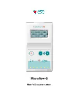
Microflow-S pocket Doppler   


User’s Documentation 


20 174 C 


Page 8/12 


Emissions RF 
CISPR 11 

Class A 

The emissions characteristics of 

Microflow-S

 make it suitable for use 

in industrial areas and hospitals (CISPR 11 class A).  
If it is used in a residential 

Microflow-S

 might not offer adequate 

protection to radio-frequency communication services. 
The user might need to take mitigation measures, such as relocating or 
re-orienting this equipment. 

Table 2 
Manufacturer’s Declaration

 – 

Electromagnetic Immunity (IEC60601-1-2) 

The 

Microflow-S

 is suitable for use in the specified electromagnetic environment. The customer and/or user 

should assure that it is used in an electromagnetic environment as described below; 

Immunity Test 

Test Level 
IEC 60601-1-2 

Compliance 
Level 

Electromagnetic 
Environment Guidance 

Electrostatic 
discharge (ESD) 
IEC 61000-4-2


± 8 kV contact 
 
± 2 kV ± 4 kV ± 8 
kV ± 15kV air


± 8 kV contact 
 
± 2 kV ± 4 kV ± 8 
kV ± 15kV air


Floor should be antistatic, wool. If floor are 
covered with synthetic materials, the 
relative humidity should be minimum at 
least 35%. 
 

Table 3 
Manufacturer’s Declaration - Electromagnetic immunity


The 

Microflow-S

 is suitable for use in the specified electromagnetic environment. The customer and/or user 

should assure that it is used in an electromagnetic environment as described below;


Immunity 
Test 

IEC 60601 test 
level 

Compliance 
level 

Electromagnetic environment - guidance 

Radiated RF 
IEC 61000-4-3


3 V/m 
80 MHz to 800 
MHz 
3 V/m 
800 MHz to 2.5 
GHz 

3 V/m 
 
 
3 V/m  

Portable and mobile RF communications equipment 
should be used no closer to any part of the 

Microflow-S

 including cables, than the 

recommended separation distance of  30cm or 12 
inches.


Note 1: 80 MHz to 2.7GHz, the higher frequency range applies. 
Note2 : These guidelines may not apply in all situations. Electromagnetic propagation is affected by 
absorption and reflection from structures, objects, and people.


a Field strengths from fixed transmitters, such as base stations for radio (cellular/cordless) 
telephones and land mobile radio, AM and FM radio broadcast, and TV broadcast cannot be 
predicted theoretically with accuracy. To assess the electromagnetic environment due to fixed 
RF transmitters, an electromagnetic site survey should be considered. If the measured field 
strength in the location in which the 

Microflow-S

 is used exceeds the applicable RF compliance level 

above, the 

Microflow-S

 should be observed to verify normal operation. If abnormal performance is 

observed, additional measures may be necessary, such as re-orienting or relocating the 

Microflow-S

Over the frequency range 150 kHz to 80MHz, field strengths should be less than 3 V/m 

Environmental data 

6.1 

Battery 

Battery type

: 9 V alkaline - 6LR61 or PP3 not rechargeable 

Battery life

: 5h charge

.


6.2 

Physical specifications 

Casing 

Width = 80 mm 


Depth = 150 mm 


Height = 40 mm 

Weight 

200 g to 300g with battery and probe  

6.3 

Doppler sound output 

Outpour power: 500mW RMS 

Summary of Contents for Microflow-S

Page 1: ...Microflow S User s Documentation ...

Page 2: ...4 3 4 Intended user profile 4 3 5 Intended conditions of use 4 3 6 Expected service life 4 3 7 Contact duration on applied parts and accessible parts 4 3 8 Contraindication 4 3 9 Essential performance 5 4 CAUTION 5 4 1 Operator 5 4 2 Storage environment 5 4 3 Operating environment 5 4 4 Electrical safety 5 4 5 Maintenance and service 6 4 6 Ultrasound field 6 4 7 Environmental protection 6 4 8 Elec...

Page 3: ...EC60417 5134 IEC60417 5109 Applied part type BF ESD sensible Not for home use ISO7000 2498 ISO7000 2493 EN980 Serial number Catalogue reference number Manufacturer ISO 7000 2497 ISO7010 M002 Follow operating instructions With manufacturing year IEC60417 5009 Stand by Battery level Blink when low Sound volume adjust IEC60417 5134 Electrostatic sensitive device 1 2 Packaging ISO7000 626 ISO7000 2606...

Page 4: ...of tissue applied to or interacted with The detachable parts of the MICROFLOW S are applied on the patient s skin mainly of the limbs fingers toes and neck 3 4 Intended user profile The device must be used by or on the order of physician 3 5 Intended conditions of use The device shall be used in the specified environmental operating conditions 3 6 Expected service life hour per day 200 days year d...

Page 5: ...please contact your Atys dealer Do not use the MICROFLOW S if the packing of the device or of the probe is damaged The MICROFLOW S must be stored and moved in its box The complementary protective packing must be used in the case of a dispatch 4 3 Operating environment Climatic environment operating 15 25 C 10 80 Hr 700 1060 Hpa Do not use the device outside the specified environment To prevent fir...

Page 6: ...gnetic compatibility Use of this equipment adjacent to or stacked with other equipment should be avoided because it could result in improper operation If such use is necessary this equipment and the other equipment should be observed to verify that they are operating normally Use of accessories transducers and cables other than those specified or provided by the manufacturer of this equipment coul...

Page 7: ...0601 1 6 5 6 Risk management The risk management is processed in compliance with ISO14971 5 7 Electromagnetic compatibility The Microflow S has been designed to work normally in conditions specified by the international standard IEC60601 1 2 2014 Information 1 Refer to the essential performance on this document Information relative to the A class limitation The MICROFLOW S emits electro magnetic p...

Page 8: ...Electromagnetic environment guidance Radiated RF IEC 61000 4 3 3 V m 80 MHz to 800 MHz 3 V m 800 MHz to 2 5 GHz 3 V m 3 V m Portable and mobile RF communications equipment should be used no closer to any part of the Microflow S including cables than the recommended separation distance of 30cm or 12 inches Note 1 80 MHz to 2 7GHz the higher frequency range applies Note2 These guidelines may not app...

Page 9: ...e red LEDs indicate flow towards the transducer and three blue LEDs flow away from it The number of lightning LEDs is related to the flow intensity Since the device is bi directional the red and blue LEDs might light simultaneously This would indicate that an artery and a vein have been located at the same time The seven LEDs light up during 1 second when the device is switched on The probe is use...

Page 10: ... the probe must be performed There must not be any cracks or upheaval 7 4 BATTERY REPLACEMENT The battery should be replaced as soon as the yellow LED flashes Respect the battery type 9 V alkaline 6LR61 or PP3 Be careful about the polarity when replacing the battery 8 Service 8 1 Microflow S spare parts Order number designation Order number designation 04 739 Loud speaker 11 830 Microflow S keyboa...

Page 11: ...l work Switch off the unit 8 5 Probe connector wiring 9 Document revision history Reference 20 174 C MICROFLOW S User s documentation March 2017 Atys 17 Parc d Arbora F69510 SOUCIEU EN JARREST France Tel 33 4 78 05 69 69 Fax 33 4 78 05 69 60 Change R date Description 04 272 A March 16 2012 Initial release 05 371 B January 2017 Phase 401 revision 05 518 C March 2017 Accessories reference update Iss...

Page 12: ...es associées associés Classification per Annex IX Class IIa Classification Annexe IX Conformity Route Annex II section 3 Annexe Annexe II point 3 We herewith declare that the above mentioned product meets the provisions of the Council Directive 93 42 EEC for the Medical devices All supporting documentation is retained under the premises of Atys 69510 Soucieu en Jarrest FRANCE Nous certifions que l...

Reviews: