


7-2
XDS-PRO (PRO1R, PRO4R & PRO1S, PRO4S) Satellite Receivers - User Guide Rev. A R830001-2106
SPECIFICATIONS
ATX
Confidential & Proprietary
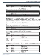
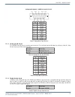
7.1.3 Relay Outputs
The receiver includes a connector port providing 16 normally open relay contact connections. There is a single connector
provided on the PRO1R and PRO1S models and two connectors on the PRO4R and PRO4S receivers. The port specification
is provided in Table 30, and the pin-outs for each in Table 31.
Connector
DB-37 Male
Contacts
16 SPST Normally Open
Format
Form A
Switching Voltage
200 Volts
Switching Current
0.5 Amps
Carry Current
1.0 Amps
Contact Rating
10 Watts
Table 30: Relay Outputs Specifications
PIN
FUNCTION
PIN
FUNCTION
1
RLY1A
20
RLY1B
2
RLY2A
21
RLY2B
3
RLY3A
22
RLY3B
4
RLY4A
23
RLY4B
5
Ground
24
Ground
6
RLY5A
25
RLY5B
7
RLY6A
26
RLY6B
8
RLY7A
27
RLY7B
9
RLY8A
28
RLY8B
10
Ground
29
RLY9B
11
RLY9A
30
RLY10B
12
RLY10A
31
RLY11B
13
RLY11A
32
RLY12B
14
RLY12A
33
Ground
15
TxData
34
RLY13B
16
RLY13A
35
RLY14B
17
RLY14A
36
RLY15B
18
RLY15A
37
RLY16B
19
RLY16A
Table 31: Relay Port Pin-Out
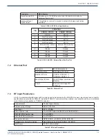
7.1.4 Analog Audio Output
The PRO4R and PRO4S have 4 analog output channels, and the PRO1S and PRO1R have one analog output channel. The
audio output port specifications are outlined in Table 32. Table 330 lists the pin-outs of the analog output connectors.
Connector
DB-9 Male
Format
Balanced Pair L, R
Range
-10 to +4dBu nominal (+22
max)
Performance
0.1% THD 85dB dynamic
range
Table 32: Analog Audio Output Specifications
CHAPTER 7:


