background image


INSTALLATION AND SAFETY CODES 

 
USA and Canada 

– follow all applicable state and local codes – in the 

absence of local codes or regulations, refer to current standards of: 


Recreation Vehicles ANSI A119.2/NFPA 501C 


National Fuel Gas Code ANSI Z223.1 and/or CAN/CGA B149  

Installation Codes 


This furnace must be installed in accordance 

with the manufacturer’s 

instructions and the manufactured Home Construction and Safety 
Standard, Title 24 CFR, part 3280, or when such standard is not 
applicable, the Standard for Manufactured Home Installations. 
(Manufactured Home Sites, Communities and Set-Ups), ANSI A255.1 
and/or CAN/CSA-Z240 MH Series M92 Canadian Standard for Mobile 
Homes.” 


ANSI A 255.1 and/or CAN/CSA-Z240.6.2 MH Series, Mobile Homes 


Ground National Electrical Code ANSI/NFPA 70 and/or CSA C22.1, 
Part 1 


Park Trailers ANSI 119.5 
 

GENERAL FURNACE LOCATION AND INSTALLATIONS 


All models can be installed in either a horizontal or vertical mounting 
position Horizontal installs must have the gas line positioned on top, 
vertical installs must have the vent located at floor level and gas line on 
the right side. 


Always install furnace exhaust system through an exterior wall. 


DO NOT install furnace near tilt-out rooms, slide-outs, doors or other 
projection that could obstruct furnace exhaust. 


Locate furnace near midpoint of coach for single furnace applications. 


Installation must provide accessibility if any repairs are necessary to 
the furnace. Failure to meet this requirement will create additional labor 
costs that will be the responsibility of the installer. 


DO NOT install vent in areas where projection or door openings come 
within 6” of vent opening. 


DO NOT install furnace in an area where wires, pipes or other objects 
will interfere with installation or operation of furnace. 


DO NOT install furnace on material that restricts return air, such as 
directly on carpet, or soft material (like vinyl). If you must install furnace 
on carpet or soft material, install furnace on cleats, or on a wood or 
metal panel extending the full width and depth of furnace plus 
minimum clearance to combustibles. 


DO NOT use petroleum or citrus type cleaner on plastic parts, as 
damage may occur. 


NOTE: The exhaust temperature of this furnace could discolor or warp 
some materials. You should verify that the material used on the coach 
door, panel, or cover will not discolor or warp from the exhaust 
temperature whenever any door, panel, or cover is in the open 
position. 


CAUTION: Due to the differences in vinyl siding, materials this 
appliance should not be installed without first consulting with the 
manufacturer of the siding or cutting the siding away from the area 
around the appliance vent. 


A gas-fired furnace for installation in a residential garage must be 
installed so the burner(s) and the ignition source are located not less 
than 18 in (457mm) above the floor and the furnace must be located or 
protected to avoid physical damage by vehicles. 

 
FURNACE INSTALLATION 


The furnace should always be installed level (front to back, side to 
side) to prevent water intrusion into the interior. 


Set aside venting and outer door parts for installing on the outside of 
coach. 


NOTE to assure sufficient return air to circulating blower maintain 
specified clearances see Table 4. 


Units can be installed with or without the interior grill. If grill is not used 
a minimum of 35 sq. in. of free return must be provided. 


If units are installed using the small outside vent system access to the 
inside of the coach must be provided directly in front of the unit to 
remove for service suggested opening size 12-

1/2” wide by 8-3/8” 

height. 


Remove knockouts from furnace and install two duct adapters for side 
discharge by inserting back flange over casing and inserting tab into 
square notch, then twist adapter 90°. 


Insert furnace into cabinet opening and secure with two screws 
through casing legs to floor. Units are secured by door or vent systems 
through the coach sidewall. 


Attach flexible ducting over duct adapters and secure. All flex ducting 
requires rating of 200°F. 


Run ducting to locations keeping bends and excess ducting to a 
minimum and secure to registers. 


Connect wiring to furnace.  See wiring connection section. 


Connect gas line to top, side or rear of furnace.  See gas connection 
Figure 6. 

 
1. 

Cut the required exterior wall opening for your venting system see 
Figure 1. 

2. 

Configure furnace for ducting option to be used refer to duct 
configurations Table 2. 

3. 

Install furnace into opening and attach ducting to adapters. 

4. 

Make gas and electrical connections, to the units. 

5. 

See door or vent installation below on how to complete the installation.  
 

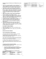
SIDEWALL CUTOUT 

Door system exterior 

wall thickness 0” to 2-1/2”. 

Small vent system 0

” to 2-1/2”. 

 
WALL CUTOUTS Table 5 


Small Vent (exterior) 

3-

1/2” Dia. 

Standard Door (exterior) 

12-1/4

” 

max 

7-1/4

” 

Max 


Front Grill (interior cabinet) 

11-

0” 

max 

7-1/4

” 

max 


Front Grill Trim Ring 

(interior cabinet) 

12-

1/2” 

max 

8-

3/4” 

max 


Figure 1


DO NOT oversize hole 

– over sizing can result in water leakage. 

Zero clearance around air intake cutout for best sealing condition. 
 

SMALL VENT INSTALLATION 


Summary of Contents for AFSAD12111

Page 1: ...DO NOT use furnace cabinet area as a storage compartment DO NOT vent furnace with venting system serving another appliance DO NOT vent furnace to an outside enclosed porch area DO NOT use for temporary heating of buildings or structures under construction Protect building materials from degrading from flue gas exhaust Protect furnace electrical components from water Compartments must be closed whe...

Page 2: ...cted 12 Volt Amperage AMPS 3 4 3 4 4 8 2 4 Power Supply Volt DC 12 12 12 12 Watts 41 41 56 34 Minimum Return Air 35 in2 35 in2 35 in2 35 in2 WC WATER COLUMN DUCTING CONFIGURATION Table 2 Models AFSD12 AFSD16 AFSD20 AFSAD12 Side Ducting 2 Ducts 2 Ducts 2 Ducts N A Front with Side Ducting 1 or 2 Ducts 1 or 2 Ducts 1 or 2 Ducts N A Front Only no Side Ducts Front Front Front Front DIMENSION Table 3 Ap...

Page 3: ...ition CAUTION Due to the differences in vinyl siding materials this appliance should not be installed without first consulting with the manufacturer of the siding or cutting the siding away from the area around the appliance vent A gas fired furnace for installation in a residential garage must be installed so the burner s and the ignition source are located not less than 18 in 457mm above the flo...

Page 4: ...h cutout about a 1 inch slip bezel around casing and flush inner flange with casing 4 Secure bezel to furnace casing with 6 screws 5 Push furnace and bezel back tight against side wall and secure with 14 screws 6 When installing screws DO NOT deform bezel 7 Connect the gas line to the valve and push the gas line plug into casing opening 8 Remove excess sealant from around bezel and visually inspec...

Page 5: ...d PROPANE GAS CONNECTION Propane Gas Pressure Test The furnace and any individual shut off valve must be disconnected from gas supply piping system during and pressure testing of system at test pressures of more than 1 2 PSI Before furnace is connected piping systems are to be tested to be leak free The test must maintain air pressure of a least 6 of mercury or 3 PSI for at least 10 minutes The en...

Page 6: ... and remain off until unit is reset by reactivating the thermostat Stop Read Users Information Manual supplied with furnace 1 Turn the manual valve if so equipped or the valve at the outside LP tank to the OFF position Do NOT force NOTE This furnace is equipped with a valve shut off switch with switch in OFF position Gas will not flow to burner nor will the furnace operate Turn switch to ON positi...

Page 7: ...7 WIRING AND LADDER DIAGRAM ...

Page 8: ...8 PART DRAWINGS PART LISTS ...

Page 9: ...9 ...

Page 10: ...10 ...

Page 11: ...lorsque vous effectuez le test NE PAS utiliser un courant alternatif de 120 V avec les modèles à courant continu NE PAS utiliser la zone du cabinet de fournaise comme compartiment de rangement NE PAS aérer la fournaise avec un système de ventilation pour entretenir un autre appareil NE PAS aérer la fournaise à un endroit extérieur fermé comme une véranda NE PAS utiliser pour le chauffage temporair...

Page 12: ...S ÉLECTRIQUES 6 INSTALLATION DU THERMOSTAT 6 INSTRUCTIONS D UTILISATION 6 POUR METTRE HORS TENSION 7 VÉRIFICATIONS DU SYSTÈME 7 SPÉCIFICATIONS MODÈLE Tableau 1 Nos de modèles AFSD12 AFSD16 AFSD20 AFSAD12 Type de gaz LP Propane LP Propane LP Propane LP Propane BTU en entrée 12 000 16 000 18 000 12 000 BTU en sortie 9 120 12 160 13 680 9 120 Conduit de pression statique 0 10 po WC 0 10 po WC 0 10 po...

Page 13: ...souples installez la fournaise sur des taquets ou sur un panneau de bois ou de métal s étendant de la largeur et profondeur complète de la fournaise plus un dégagement minimal pour les combustibles NE PAS utiliser de nettoyant à base de pétrole ou de type citron sur les pièces de plastique vous pourriez les endommager ATTENTION À cause des différences dans les matériaux de revêtement en vinyle cet...

Page 14: ...e dans le calfeutrage et inspectez visuellement le conduit pour vous assurer qu il est bien scellé fixez avec deux conduits et deux vis et retirez l excès de calfeutrage INSTALLATION STANDARD DE LA PORTE Figure 3 Toutes les surfaces en contact avec l extérieur du mur latéral doivent être étanches et scellées avec un scellant RTV Les conduits sont conçus pour permettre l évacuation d eau lorsqu ins...

Page 15: ...s de tuyauterie flexible Suivez les configurations de tuyauterie dans le tableau 2 Évitez des extrémités tranchantes ou des conduits écrasés Étirez tous les conduits et branchez les directement aux sorties gardant la quantité et les angles de tuyaux pliés au minimum 1 Retirez le plateau de déboucheur des sorties désirées See Figure 6 Si les deux sorties de 4 po ne sont pas utilisées laissez les en...

Page 16: ...19 17 11 16 87 65 52 43 37 33 29 26 17 Cette fournaise est conçue pour une mise à la terre négative de 12 V à courant continu seulement NE PAS essayer de modifier la fournaise pour un système de mise à la terre positif ou connecter la fournaise directement à un courant alternatif de 120 V Les dommages sur les composantes de la fournaise se produiront et la garantie sera annulée Utilisez un fil de ...

Page 17: ... éteignez l unité et contactez votre revendeur ou une agence locale de véhicules récréatifs Ne pas continuer faire fonctionner la fournaise par le thermostat espérant avoir une ignition POUR METTRE HORS TENSION 1 Mettez le thermostat au réglage le plus bas puis déplacez le levier dans la position ARRÊT 2 Tournez la valve manuelle d arrêt si équipé à la position ARRÊT Ne pas forcer VÉRIFICATIONS DU...

Reviews: